Quantcast
Channel: Well Control – Drilling Formulas and Drilling Calculations
Viewing all 117 articles
Browse latest View live

What is Closing Ratio in Blow Out Preventor (BOP)?

$
0
0

People asked me about what the closing ratio is and what it tells us. Closing ratio is defined as the cross sectional area of the ram piston (cylinder) divided by the cross sectional area of the ram shaft. The closing ratio is used to determine Ram closing pressure which will overcome wellbore pressure acting to Ram body.

Closing Ratio = Ram Piston Area ÷ Ram Shaft Area

Before going into the detailed calculation, we would like to show you where the cylinder and the ram shaft are in BOP. In Figure 1, the yellow shaded parts demonstrate these two areas which will be used to calculate the closing ratio.

 Figure 1 - Shaffer SL-Ram BOP

Figure 1 – Shaffer SL-Ram BOP

Example: Ram has a piston cylinder of 12 inch and 4” of ram shaft (see Figure 2).

Ram piston area = (π x 122 ) ÷ 4 = 113.1 square inch

Ram shaft area = (π x 42 ) ÷ 4 = 12.6 square inch

Closing Ratio = 113.1 ÷ 12.6 = 9.0

Figure 2 - Basic Diagram of Rams

Figure 2 – Basic Diagram of Rams


How To Use Closing Ratio To Determine Minimum Operating Pressure

When you know the closing pressure of the BOP ram, you can use the figure to determine the minimum operating pressure. The following equation is used to determine the minimum operating pressure from the accumulator unit (koomey).

Minimum Operating Pressure = Working Pressure ÷ Closing Ratio

 Example: What is the minimum operating pressure would be needed to close the ram against 10,000 psi maximum anticipated pressure on BOP? Please use the ram details from the example above.

Minimum Operating Pressure = 10,000 ÷ 9 = 1,111 psi

With operating pressure of 1,111 psi, hydraulic force will equal to force acting from the wellbore in this case (see Figure 3).

 Figure 3 - Force Acting at Ram Shaft and Force At Piston

 Figure 3 – Force Acting at Ram Shaft and Force At Piston

In this case, a standard accumulator (3,000 psi system) with minimum operating pressure of 1,200 psi is good enough to shut the well in with 10,000 psi surface pressure.

Reference book: Well Control Books


Casing Shoe Pressure While Circulating Influx in Well Control Situation

$
0
0

Many people ask us a lot of questions regarding shoe pressure while circulating kick (wellbore influx) out of the wellbore. We will summarize all the scenarios to help you get clearer picture. There are a total of three cases which we will separately discuss as per the details below.

Note: All the calculations and scenarios are based on water based mud and gas kick.

 First Scenario – Top of Gas Kick Below Casing Shoe


Figure 1 - Top of Gas Kick Below Casing Shoe

Figure 1 – Top of Gas Kick Below Casing Shoe

As you can see in Figure 1, hydrostatic pressure above the casing shoe remained constantly because the fluid column is the same. The overall hydrostatic pressure in the well will decrease because gas expansion when it is being circulated. In order to maintain the bottom hole pressure constant, casing pressure will increase to balance the loss of hydrostatic pressure in the wellbore due to expansion.

The equation below is relationship between hydrostatic pressure, casing pressure and bottom hole pressure.

Bottom Hole Pressure = Casing Pressure + Hydrostatic Pressure in Annulus

 Let’s take a look at casing shoe and we can write the relationship as follows;

Pressure at Casing Shoe = Hydrostatic Pressure Above Shoe + Casing Pressure

If the gas influx is still below the casing shoe, the hydrostatic pressure is the same and the casing pressure will increase; therefore, pressure at shoe will increase and the shoe pressure will reach the highest pressure when the gas influx reaches the casing shoe.

Conclusion: Casing shoe pressure will increase until the top of the bubble reaches the casing shoe.

Second ScenarioShoe Pressure When the Gas Kick Passing Shoe

For this case, we will consider the shoe pressure when the gas kick is passing the casing shoe (see Figure 2).

Figure 2 - Shoe Pressure When the Gas Kick Passing Shoe

Figure 2 – Shoe Pressure When the Gas Kick Passing Shoe

Let’s apply the hydrostatic pressure concept.

The formula for the bottom hole pressure is listed below:

Bottom Hole Pressure = Pressure at Casing Shoe + Hydrostatic Pressure Underneath Casing Shoe

While circulating kick, we keep the bottom hole pressure constant therefore the equation will look like this

 Bottom Hole Pressure (constant while circulating) = Pressure at Casing Shoe + Hydrostatic Pressure Underneath Casing Shoe

While the gas kick is passing the shoe, the hydrostatic pressure in the open hole underneath casing shoe will increase because mud column underneath the shoe increases. Therefore, in order to maintain bottom hole pressure constant, the shoe pressure will decrease.

Note: we don’t select use the same equation in the first scenario (Pressure at Casing Shoe = Hydrostatic Pressure Above Shoe + Casing Pressure) to analyze shoe pressure for this case because of following issues;

  1. Hydrostatic pressure always decreases while the gas moves up.
  2. Casing pressure always increases while the gas moves up.

Therefore we cannot make find the definite answer regarding shoe pressure from the equation used in the first scenario.

Conclusion: Pressure at shoe will decrease when gas bubble passing the shoe.

Third ScenarioShoe Pressure When Gas Kick Above Shoe


The last scenario is shoe pressure when gas is above the casing shoe (see Figure 3).

Figure 3 - Shoe Pressure When Gas Kick Above Shoe

Figure 3 - Shoe Pressure When Gas Kick Above Shoe

Again let’s apply the hydrostatic pressure concept,

Bottom Hole Pressure = Pressure at Casing Shoe + Hydrostatic Pressure Underneath Casing Shoe

The concept while circulating kick is the same. It means that you must keep bottom hole pressure constant. Therefore, you can write the equation like this:

BHP (constant while circulating) = Hydrostatic Pressure at Shoe + Hydrostatic Pressure Underneath Casing Shoe

Re-arrange the equation like this;

Hydrostatic Pressure at Shoe = BHP (constant while circulating) – Hydrostatic Pressure Underneath Casing Shoe

While kick is above the shoe, the hydrostatic pressure below the casing shoe will remain constant because there is no change in fluid density. Therefore, casing shoe pressure will remain constant once the gas is above the shoe.

Conclusion: Shoe pressure will remain constant after the gas kick is above the casing shoe.

Summary:

Shoe Pressure When the Gas Kick Passing Shoe => Casing shoe pressure will increase until the top of the bubble reaches the casing shoe.

Shoe Pressure When Gas Kick Above Shoe => Pressure at shoe will decrease when gas bubble passing the shoe.

Shoe Pressure When Gas Kick Above Shoe => Shoe pressure will remain constant after the gas kick is above the casing shoe.

Reference book: Well Control Books

Basic Pressure Control – VDO Training

$
0
0

As you know well control is very important subject in drilling industry and in order to understand it clearly, you need to understand basic principle. This time we would like to share this excellent VDO showing the basic pressure control of drilling process. It is just only five minutes but it will give you details plus illustration for more understanding. Additionally, we also add full VDO transcript for anyone who cannot catch the VDO content.

This is the VDO transcript from our team.

basic pressure control

Fluids in a formation are under pressure. When drilled, this pressure can escape to the surface if it is not controlled. Normally, drilling mud offsets formation pressure, that is the weight or pressure of the drilling mud keeps fluids in the formation from coming to the surface.

For several reasons however, the mud weight can become lighter than is necessary to offset the pressure in the formation. When this situation occurs, formation fluid enters the hole. When formation fluids enter the hole, this is called a “kick”.
A blowout preventer stack is used to keep formation fluids from coming to the surface. These are called BOP’s. By closing off a hole in this equipment the rig crew can seal off the hole. Sealing the hole prevents more formation fluid from entering the hole. With the well sealed or shut-in, the well is under control.
Rig crews was you was a service BOP system on land rigs, jack up rigs, submersible rigs and platform rigs. They use a sub-sea BOP system on off shore floating rigs like semi-submersibles and drill ships.
A blowout is dangerous. Formation fluids like gas and oil rise to the surface and burn. Blowouts can injure or kill destroy the rigs or the environment. Rig crews therefore train and work hard to prevent blowouts. Usually they are successful, so blow outs are rare but when they happen they spectacular and thus often make the news.
A kick is the entry of formation fluids into the well bore while drilling. Kick occurs when the pressure exerted by the drilling mud is less than the pressure in the formation of the drill string is penetrating. The mud that circulates down the drill string and up the hole is the first line of defense against kicks. Drilling mud creates additional pressure as it circulates. The mud pressure keeps the formation pressure from entering the well bore. On the rig, it is said that the mud keeps the well from kicking.
Sometimes however crew members may accidentally allow the mud level or the weight in the hole to drop. This drop in weight or level can happen for several reasons. For example the crew may fail to keep the hole full of mud, may pull the pipe out of it or they may pull the pipe tool fast which can lower the bottom hole in pressure. When the mud level or at the mud weight drops the pressure exerted on the formation decreases. If either happens formation fluids can enter the hole. If they do the well takes a “kick.”
In other words when the formation weight exceeds the pressure of the mud column then the well can kick. To keep a kick from becoming a blowout the rig crew uses blowout prevention equipment.

API Ring Gaskets Used in BOP Connections

$
0
0

There are several API types of ring gaskets used in BOP connections and this is very important to personnel involving in drilling operation to know about it. API 6A: Specification for Wellhead and Christmas Tree Equipment is the standard which every manufacture refers to their equipment.

API Type R Ring Gasket

The API type “R” rig gasket is not a pressure energized gasket therefore this type does NOT recommend for BOP equipment or safety critical equipment as x-mas tree, wellhead valves, etc. Sealing area is along small bands of contact between the gasket and the ring gasket on both ID and OD of the gasket. Shape of type “R” may be oval or octagonal in cross section (see Figure 1). Additionally, face to face between flanges will not touch when the flanges are tightened (see Figure 2). The “R” gasket is compatible for 6B flanges.

 Figure 1 - Type R ring gaskets (shape and groove)


Figure 1 - Type R ring gaskets (shape and groove)

Figure 2 - Type R Gasket When Energized

Figure 2 - Type “R” Gasket When Energized

API Type “RX” Ring Gasket

RX ring gasket is a pressure energized ring joint gasket and sealing area when energized is along small bands of contact between the groove and the OD of the ring gasket (see Figure 3). This gasket is manufactured a little bit bigger in diameter than the ring groove therefore when it is compressed, it will deform and seal the pressure. The “RX” is also not a face to face contact (see Figure 4). This gasket must be utilized only one time. The “RX” gasket is compatible for 6BX flanges and 16B hubs.

 Figure 3 - Type RX Ring Gasket (Shape and Groove)

Figure 3 - Type RX Ring Gasket (Shape and Groove)

Figure 4 - Type RX Gasket When Energized

Figure 4 - Type “RX” Gasket When Energized

API Face-to-Face Type “RX” Ring Gasket

The face-to-face “RX” ring gasket is similar to “RX” gasket except it has increased groove width to ensure face to face contact between flanges or hubs (see Figure 5). However, this leaves the gasket unsupported on its ID. It is pressure-energized gasket which was adopted by API. This gasket may not remain in a perfect round shape when it is tightened because it does not have the support from ID of the ring groove.

 Figure 5 - Face-to-Face Type RX Ring Gasket

Figure 5 – Face-to-Face Type “RX” Ring Gasket

API Type “BX” Ring Gasket

API Type “BX” (Figure 6) is a pressure energized ring and it is designed for face-to-face contact between hubs or flanges. When energized, small contact bands between OD of the ring gasket and the rig groove is the sealing area. This ring gasket is slightly bigger than the ring groove. Therefore, when the hubs or flanges are tightened, the gasket will be slightly compressed into the rig groove to seal pressure (see Figure 7). Since this is face-to-face contact type, the tolerance of the gasket and ring groove is vital. If you have the gasket at the high side of tolerance and the groove at the low side of tolerance, it will be quite difficult to achieve face-to-face contact. The “BX” gasket is compatible for 6BX flanges and 16BX hubs.

Figure 6 - API Type BX Ring Gasket

Figure 6 - API Type “BX” Ring Gasket

 Figure 7 - API Type BX Ring Gasket When Energized

Figure 7 – API Type “BX” Ring Gasket When Energized

 Reference book: Well Control Books

Why Do We Need To Minimize Influx (Kick)?

$
0
0

As you know, we’ve always been trained or told to minimize influx (kick). Nowadays, there are several tools and procedures guiding us to prevent large influx; however, interestingly there are quite a lot of people who don’t understand why we need to do this. In this topic, we will demonstrate how kick volume will affect wellbore and surface casing pressure.

Why-Do-We-Need-To-Minimize-Influx-(Kick)

Main concept of minimizing kick coming into the wellbore is to minimize surface casing pressure when shut in. If you have excessive surface casing pressure, you will have a chance to fracture the weakest formation in the wellbore such as formation at casing shoe. You need to remember that more influx equals to more surface pressure. We will do basic calculation to see the effect of kick volume and surface pressure.

Example: Use the following information and compare the result of 2 cases.

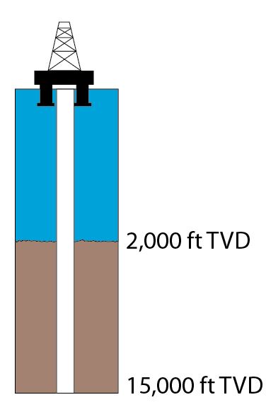
Well Information (figure 1)

Figure 1 - well info

Figure 1 - Well Information

  • 9-5/8” casing shoe was set at 5,000’MD/5,000’TVD.
  • The well is drilled to 10,000’MD/10,000’TVD with 8.5 bit.
  • The well is assumed to be a gauge hole.
  • Current mud weight is 9.2 ppg water based mud.
  • Leak off test performed at 9-5/8” casing shoe is 13.5 ppg equivalent.
  • Reservoir pressure at 10,000’ TVD is 10.5 ppg equivalent.
  • Average gas gradient is 0.1 psi/ft.
  • 5” DP is used to drill this section and 6-1/2” DC is used as BHA for 1,000 ft.

What will happen if the wellbore influx is 10 bbl and 50 bbl?

First of all, we need to determine influx height of 10 bbl and 50 bbl.

Influx Height = Kick Volume ÷ Annular Capacity

Annular Capacity between 8-1/2” hole and 5” DP = (8.52 – 52) ÷ 1029.4 = 0.04590 bbl/ft

Annular Capacity between 8-1/2” hole and 6.5” DC = (8.52 – 6.52) ÷ 1029.4 = 0.02194 bbl/ft

Height of 10 bbl

Influx Height @ 10 bbl = 10 ÷ 0.02194 = 343 ft

 Figure 2 - Height of 10 bbl kick

Figure 2 – Height of 10 bbl kick

Height of 50 bbl

For this case, we need to check see if 50 bbl will be more than annular volume between hole and drill collar.

Volume between hole and 6.5” DC = Annular Capacity x DC Length

Volume between hole and 6.5” DC = 0.02914 x 1,000 = 29.14 bbl

As you can see from the figure, it tells us that there is kick volume in the annulus between hole and 5” DP.

Kick Volume between Hole and 6.5” DC = Total Kick Volume – Volume between hole and 6.5” DC

Kick Volume between Hole and 6.5” DC = 50 – 29.14 = 20.86 bbl

We know that we will have 20.86 bbl of kick between hole and 5” DP and then we need to calculate height of that volume.

Influx Height @ 20.86 bbl = 20.86 ÷ 0.04590 = 454 ft

Total Influx Height = Influx Height between DC and Hole + Influx Height between DP and Hole

Total Influx Height = 1000 + 454 = 1454 ft

 Figure 3 - Height of 50 bbl kick

Figure 3 – Height of 50 bbl kick

What is formation pressure at 10,000’MD/10,000TVD?

Formation pressure = 0.052 x 10.5 x 10,000 = 5,460 psi

What is Maximum Initial Shut-in Casing Pressure (MISICP)?

Maximum Initial Shut-in Casing Pressure (MISICP) = (LOT – Current MW) x 0.052 x Shoe TVD

Maximum Initial Shut-in Casing Pressure (MISICP) = (13.5 – 9.2) x 0.052 x 5,000 = 1,118 psi

Then we need to apply the hydrostatic pressure concept to determine casing pressure as per the relationship below.

Formation Pressure = Hydrostatic Pressure + Casing Pressure

Re-write to the equation below

Casing Pressure = Formation Pressure – Hydrostatic Pressure

Hydrostatic Pressure with 10 bbl of Kick in The Well

Hydrostatic Pressure = Hydrostatic from Gas + Hydrostatic from Mud

Hydrostatic Pressure = (Gas Gradient x Height of Gas) + (0.052 x MW X Height of Mud)

Hydrostatic Pressure = (0.1 x 343) + (0.052 x 9.2 x (10,000 – 343)) = 4,654 psi

Casing Pressure with 10 bbl of Kick in The Well

Casing Pressure = 5,460 – 4,654 = 806 psi (Figure 4)

Figure 4 - Casing Pressure with 10 bbl gas kick

Figure 4 – Casing Pressure with 10 bbl gas kick

Hydrostatic Pressure with 50 bbl of Kick in The Well

Hydrostatic Pressure = Hydrostatic from Gas + Hydrostatic from Mud

Hydrostatic Pressure = (Gas Gradient x Height of Gas) + (0.052 x MW X Height of Mud)

Hydrostatic Pressure = (0.1 x 1454) + (0.052 x 9.2 x (10,000 – 1545)) = 4,233 psi

Casing Pressure = 5,460 – 4,233 = 1,227 psi (Figure 5)

Figure 5 - Casing Pressure with 50 bbl gas kick

 Figure 5 - Casing Pressure with 50 bbl gas kick

Based on the same assumption, we will get the surface pressure as listed below

Casing Pressure with 10 bbl kick = 806 psi

Casing Pressure with 50 bbl kick = 1,227 psi

If we compare with MISICP of 1,118 psi from the calculation above, we will see that 50 bbl kick will break the casing shoe (Figure 6).

Figure 6 - Shoe Fracture

Figure 6 - Shoe Fracture

Conclusion

More Kick = More Surface Pressure = Less Safe

Less Kick = Less Surface Pressure = Safer

 Reference book: Well Control Books

Basic Blow Out Preventer – VDO Training

$
0
0

Blow Out Preventer is one of the most critical equipment on the rig therefore it is very important that you need to understand it. This VDO demonstrates the basic of BOP with a lot of colorful pictures which will help you learn about it. We also add full VDO transcript in order to help people fully understand this topic. We wish you would love this.

Full VDO Transcript Deails

BOP-basic-fb

The blowout preventer, BOP stack, consists of several large valves stacked on top of each other. These large valves are called blowout preventers. Manufacturers rate BOP stacks to work against pressures as low as 2m000 pounds per square inch or psi and as high as 15,000 psi. That is about 14,000 kPa to over 100,000 kPa.

Rigs usually have two kinds of preventers, on top is an annular preventer it is called an annular preventer because it surrounds the top of the well bore in the shape of a ring or an annulus. Below the annular preventer are ram preventers. The shutoff valves in RAM preventers close my forcing or ramming themselves together.

The choke line is a line through which well fluids flow through the choke manifold when the preventers are closed. Even though the preventers shut in the well the core members must have a way to remove or circulate the kick in the mud out of the well. When the BOP shut in the well, mud and formation fluids exit through the choke line to the choke manifold. The manifold is made up of special piping and valves. The most important valve is the choke.

The choke is a valve that has an adjustable opening. Crew members circulate the kicks to the choke to keep back pressure on the well. Keeping the right amount of back pressure prevents more tick fluids from entering the well. At the same time they can get the kick out of the well and putting heavier mud to kill the well, that is, regain control of it. The well fluids leave the choke manifold and usually go to a mud-gas separator.

A mud-gas separator separates the mud from the gas in the kick. The clean mud goes back to the tanks, the gas is flared or burn a safe distance away. When the well takes a kick and the BOPs are open, well fluids force mud to flow the well bore and into the BOP stack. When the driller closes the annular BOP, flow stops. Usually drillers close the annular BOP first. The closed annular BOP diverts the flow of the choke like which goes to the choke manifold. The driller can open a line on the choke line and safely circulate the kick through the choke manifold.


Shale Gas Rig On Fire

$
0
0

This is information which I got from my friends and I would like to share with you in order to emphasize the important of well control. I am not sure about the rig name. See photos and details below;


On Tuesday at around 4:16 pm local time, there has been an explosion and fire at Nabors Drilling Rig owned that worked for Whiting Petroleum, in the state of McKenzie, North Dakota. At that time a new rig drill depth of 15,000 feet, then there is pressure from the kick in the hole with a material that causes bursts of fire. Fire Brigade was spraying foam to extinguish it. A worker named Brian Busby suffered burns on his hands and his head and was rushed to the General Hospital in the town of Watford McKenzie to get treatment.

Source: Facebook.com

Well control is very important so we would like you to learn some well control information from our website and we also provide well control quiz for free.


Basic Understanding of Sub Sea BOP VDO Training

$
0
0

Sub Sea BOP is one of the most critical well control equipment in deep water drilling and it is a good topic for everybody working on the rig to learn.

Sub-sea-BOP-equipment-fb-size

Today, we would like to share a valuable VDO training regarding the basic of sub sea BOP. Additionally, we provides learner full VDO transcript to accelerate your learning curve.

Basic Understanding of Sub Sea BOP VDO Transcript

Subsea BOP equipment is similar to a surface stack. There are however some very important differences. This section discusses these differences.

Subsea stacks attached to the well head on the seafloor meanwhile the rig floats on the water hundreds of thousands of feet or meters above. Major parts include;

BOP stack – this is a lot like a surface BOP stack. Other parts are different however, here is the flexible, or ball joint the marine riser with the choke line and kill line, guidelines, the telescopic joint with riser tensioners, the hose bundle and two control pods.

The generic controls the subsea BOP valves from an electric BOP control panel on the rig. This subsea hose bundle carries control signals and the hydraulic fluid from the rig down to the control pod and selected subsea BOP valves.

Marine riser pipe with special pipes and fittings.

It fills from the top of the subsea BOP stack and the drilling equipment located on the floating rig. Crew members run the drill string into the hole inside the riser pipe. The riser pipe also conducts drilling fluid up to the rig. Manufactures attach two smaller pipes called the choke and kill lines to the outside. Crewmembers use them to control the well during a kick or special operations.

Guidelines guide and help position equipment such as the BOP stack to ocean floor. The flexible joint cuts down on bending stresses from the riser pipe and BOP. The telescopic joint compensates for the vertical motion of the floating rig. Crewmembers also attach the riser tensioning system to it.

Riser tensioner lines support the riser pipe. The riser and guideline tensioners put constant tension on the riser pipe and guidelines. This tension suspends the riser pipe. It also compensates for the movement of the rig caused by wave action. Riser tensioning systems usually range in capacity to over 300,000 to almost 1,000,000 pounds and 135,000 to 455,000 kg with 50 feet or 50 m of wire line travel. They utilize up to 12 compression loaded tensioners that use air pressure for compensation.


4-Way Valve Operation in Blow Out Preventer Accumulator (Koomey) Unit

$
0
0

4-way valves in the accumulator (Koomey) unit are used to control the position of Blow Out Preventer (BOP). Today we will go into the detail of 3 positions of 4-way vales in order to see how each position affects to the BOP.

4-way valve operation fb

Read more details about Koomey Unit here =>mechanism of Koomey unit.

Four-Way Vale in Open Position

When the valve is turned into the open position, it directs hydraulic pressure from the manifold into the BOP openning port therefore the BOP is in the open position. The hydraulic fluid in the ram closing chamber will return back to the reservoir tank. Figure 1 illustrates how the hydraulic pressure is lined up to open the BOP.

 4-way-vale-open-rams

Figure 1 - Open position of the 4-way valve


Four-Way Vale in Closed Position

The valve is turned into the close position. It means that the hydraulic pressure from the manifold is transferred into the BOP close port. The hydraulic from the opening chamber will return back to the reservoir tank. Figure 2 shows how the hydraulic pressure is lined up to close the BOP.

4-way-vale-closed

Figure 2 - Closed position of the 4-way valve

Four-Way Vale in Block Position

When the four-way valve is left in the block position (central position – Figure 3), there is no hydraulic pressure going into either the “close” or “open” port in the BOP.  You might not know exactly the position of the rams with the block position.

 4-way-vale-block-rams

Figure 3 – Block position of the 4-way valve

In normal drilling operation, you should never leave in the block position. However, the valves can be left in the block position during rig move and repairing operation.

There is one special thing which personnel must consider about the handle of 4-way valve used to operation the bilnd/shear rams (Figure 4). The control handle must be protected to mitigate unintentional operation however it still allows to be remotely operated from the BOP remote control panel.

blind-shear-ram-handle

Figure 4 - Blind/shear ram 4-way valve handle

Reference books: Well Control Books

Bullheading Well Control Method

$
0
0

Bullheading is one of the well control methods which may be utilized in some occasions in order to control the well. Concept of bullheading is to pump kicks back into formations by using kill weight fluid. People usually use this method when normal circulation is impossible and volumetric method is not feasible to perform.

bullheading-Well-Control-Method-cover

When May You Consider Using the Bullheading Well Control Method?

  • When the kick size is very big so you may not be able to control the excessive volume coming to the surface.
  • When you need to reduce surface pressure in order to start further well control operations.
  • When there is a possibility to exceed surface pressure and volume gas on the surface if the conventional methods (drillers’ method, wait and weight and volumetric) are performed.
  • When there is no pipe in the hole while taking influx.
  • The influx contains high level of H2S which can cause safety of personnel on the rig.
  • When there is no feasible way to strip back to the bottom in order to kill in the flux below.

For every drilling operation, decision to perform bullheading must be discussed because if the well is shut in and wait for a long time before making decision to bullhead the well, it might be very difficult to perform because the surface pressure at that time may increase so high due to gas migration. The chance of pushing the kick back into reservoir becomes smaller.

 Note: Bullheading may or may not fracture formations.

There are some factors affecting the feasibility of bullheading as listed below;

Reservoir permeability – pumping fluid back into low permeability reservoir takes longer time than pumping into high permeability zone. It might require breaking the formation in order to successfully bullheading the well.

Surface pressure rating – rating of surface equipment as BOP, wellhead, casing, etc will limit the maximum allowable pumping pressure.

Type of influx – Gas influx will migrate and it will increase surface pressure, however, liquid influx (oil or water) will not cause increasing in surface pressure because it will not migrate.

Procedure of Bullheading (Example)

This procedure below will give you only overview of how to perform bullheading therefore you must need to add the site specific information before conducting the actual work.

  1. Determine surface pressure limitation of surface equipment.
  2. Calculate surface pressure which will fracture formation during  bullheading operation.
  3. Prepare a bullheading pressure chart representing strokes pumped vs pumping pressure.
  4. Ensure correct line up.
  5. Bring the pump to speed at low rate to overcome surface pressure.
  6. Slowly increase pump rate to the planned pump rate.
  7. Closely monitor tubing, casing pressure to ensure that pressures will not exceed the equipment limitation at any stage of operation.
  8. Slow down pump rate when the kill fluid close to reservoir. You will see surface pressure decrease over time while pumping kill mud into the well because the kill weight mud will increase hydrostatic pressure.
  9. Observed pressure increase when the kill weight fluid is pushed into formation.
  10. Shut the pump down and shut in the well.
  11. Monitor pressure. Bleed trapped pressure if required.

We wish you would get more understanding about the bullheading well control. Additionally, we will demonstrate some calculations related to this topic. Please feel free to leave any comments.

Reference books: Well Control Books

Fracture Gradient Reduction Due to Water Depth

$
0
0

Fracture gradient is one of the critical information which drilling engineers need to know in order to design drilling programs. For the well control stand point, the fracture gradient directly affects on how much influx volume can be successfully contained in the wellbore. If the wellbore pressure is over the fracture pressure, formations would be broken down and this situation will result in loss of drilling fluid into formations. Additionally, it might lead to well control situation because of loss of hydrostatic pressure. Fracture gradient is quite straight forward for land operation because it will not be reduce due to water column. However, the fracture gradient will be reduced in deepwater environment. In this article, we will discuss why water depth can cause the reduction in fracture gradient.

Fracture Gradient Reduction Due to Water Depth

Basically, the fracture gradient is related to fluids occupying in pore spaces of rock and weight of rock which are called overburden pressure. Generally, the overburden of a typical sedimentary is about 1.0 psi/ft (19.2 ppg). Rocks will be fractured when the wellbore pressure exceeds the confining stresses acting on it. If we make a general assumption that the overburden pressure causes the minimum confining stress of the rock. Then the formation fracture gradient will not be 1.0 psi/ft if the location is offshore.

Note: this assumption is made in order to help you get more understanding on how and why water depth can decrease the formation fracture gradient.

Why does the water depth reduce fracture gradient?

Water has less density than rock and when it is calculated into overburden pressure, it will reduce overall overburden pressure. For the calculations in this article, we will use 1.0 psi/ft as the overburden of the rock.

Let’s take a look at the examples below;

1st Example – Comparison between land and offshore location at 4,000’ TVD.

Land operation at 4,000’ TVD (Figure 1)

reduce fracture gradient 1

Figure 1 – Land operation at 4,000’ TVD


Overburden at 4,000’ TVD = 4,000 x 1 = 4,000 psi

Convert 4,000 psi at 4,000’ TVD in to ppg = 4,000 ÷ (0.052 x 4,000) = 19.23 ppg

Offshore operation at 4,000’ TVD with a water depth of 2,000 ft (Figure 2)

Water density is 0.45 psi/ft.

reduce fracture gradient 2

Figure 2 – Offshore operation – 2000 ft water depth

 Overburden pressure = (0.45 x 2,000) + (1.0 x 2,000) = 2,900 psi

Convert 2,900 psi at 4000’ TVD in to ppg = 2,900 ÷ (0.052 x 4,000) = 13.94 ppg

From the first example, you will see that at 4,000’ TVD, water depth will reduce the overburden from 19.23 ppg to 13.94 ppg.

2nd  Example – Comparison between land and offshore location at 15,000’ TVD.

Land operation at 15,000’ TVD (Figure 3)

Overburden at 15,000’ TVD = 15,000 x 1 = 15,000 psi

Convert 15,000 psi at 15,000’ TVD in to ppg = 15,000 ÷ (0.052 x 15,000) = 19.23 ppg

reduce fracture gradient 3

Figure 3 – Land operation at 15,000’ TVD

Offshore operation at 15,000’ TVD with a water depth of 2,000 ft (Figure 4)

We will use the same water depth of 2,000 ft but the well depth is at 15,000’ TVD for offshore operation.

reduce fracture gradient 4

Figure 4 – Offshore operation at 15,000’ TVD

Overburden pressure = (0.45 x 2,000) + (1.0 x 13,000) = 13,900 psi

Convert 2,900 psi at 4000’ TVD in to ppg = 13,900 ÷ (0.052 x 15,000) = 17.82 ppg

As you can see in the second example, the overburden of the formation still decreases due to water depth. However, it has less effect than the shallow well.

Conclusion

Water depth will reduce the formation fracture pressure and offshore wells will have smaller margin between mud weight and fracture pressure than land wells because of water depth effect. At the same water depth, the fracture pressure at the shallower section will be decreased more than the deeper depth. What’s more, particularly at a shallow depth where the average overburden is greatly reduced by water column, more casing strings are required to reach the plan casing depth.

Reference books: Well Control Books

Hard Shut-In Procedure while Drilling with a Subsea BOP Stack

$
0
0

Nowadays, deepwater drilling is one of the important parts of drilling in the world and there are a lot of ongoing deepwater operations. Our team will start focus on subsea well control and this topic is about hard shut in procedure while drilling with a subsea stack. This is quite similar to surface stack but it is quite tricky how you space out the well properly because the BOP is way down below approximately thousand feet from sea surface.

Shut-In Procedure while Drilling with a Subsea BOP Stack

There are 3 steps which are space out, shut down and shut in and the details for the procedure are below.

1st step: Space Out

  • Stop drilling, pick up off bottom and space out to ensure that the tool joint will not be located across the BOP. Personnel need to pre calculate where to space out because the position on the rig floor will affect where the tool joint down hole.

2nd step: Space shut down

  • Shut down pumps

3rd step: Shut-in the well

  • Shut the well in on the top most BOP as annular preventer first and then open the upper choke valve against a fully closed choke manifold valve.
  • Confirm well is properly shut in and double check line up.  Check the accumulator unit to ensure that there is no leakage after closure of the BOP.
  • Inform rig supervisors and start record data as pit gain, Shut In Casing Pressure, Shut In Drill Pipe Pressure.

Reference books: Well Control Books

Shut-In Procedure while Tripping with a Subsea BOP Stack

$
0
0

After we publish this article “Hard Shut-In Procedure while Drilling with a Subsea BOP Stack”, there are some people asking us about what about the shut-in procedure while tripping with a subsea stack. So today we will focus on this topic.

 shut-In-Procedure-while-Tripping-with-a-Subsea-BOP-Stack

For the shutting in procedure with subsea stack, there are 3 steps which are stab valve, space out, and shut in and the details for the procedure are below.

 1st step: stab valve

  • Stab the full opening safety valve into the string and then make it up to the drillstring. Close the valve.

2nd step: space out

  • Space out to ensure that the tool joint will not be located across the BOP. Personnel need to pre calculate where to space out because the position on the rig floor will affect where the tool joint down hole.

3rd step: Shut-in the well

  • Shut the well in on the top most BOP as annular preventer first and then open the upper choke valve against a fully closed choke manifold valve.
  • Confirm well is properly shut in and double check line up.  Check the accumulator unit to ensure that there is no leakage after closure of the BOP.
  • Inform rig supervisors.
  • Prepare to strip back to the bottom.

Reference books: Well Control Books

Introduction To Well Control for Horizontal Wells

$
0
0

Currently, horizontal wells are widely drilled around the world because the production from the horizontal  wells is outperform normal vertical or deviated wells at the same location. The productivity of the well increases because of longer penetration into a pay zone and/or more intersection of reservoir fractures (see Figure 1) .

 Introduction To Well Control for Horizontal Wells 1

Figure 1: A normal well and a horizontal well

Well control for the horizontal wells has the same fundamental principle during the circulation of influx from the well.  There are some corrections which adjust for frictional pressure between true vertical depth and measure depth since the horizontal wells usually have very long depth in comparison to wellbore true vertical depth.

Introduction-To-Well-Control-for-Horizontal-Wells-cover

Driller’s method is a preferred method for horizontal well control because it does not require drill pipe pressure schedule. Personnel can start circulate the first circulation to remove kick and displace the well with kill weight fluid using the second circulation method. However, if Wait and Weight method is planned to used, personnel should use a well control kill sheet with horizontal well feature to simulate the profile. It is very difficult to determine drill pipe schedule because there are several factors associated with calculations as well bore profile, size of pipe, hole size, etc.

Performing the well control in the horizontal wells is similar to normal wells but you need to understand about the hydrostatic change when the gas kick moves from a horizontal section to a vertical section. This make casing pressure profile increase drastically when compared to vertical or deviated wells.

Kick detection in horizontal wells is quite similar to the detection in vertical and deviated wells. Personnel need to use three positive kick indicators (pit gain, flow when pump off and flow show increase) to determine the influx.  Typically, drilling horizontal well usually drills into one formation therefore without any change in drilling parameters you should not see any changes in ROP. Therefore, indications of change in formation as ROP, LWD, torque and drag are very helpful for early kick indication because the changes indicate that you are in new zone which may have difference in reservoir pressure.

In the horizontal hole section, it is very difficult to immediately detect the kick because the kick is at the same TVD level. You will notice the wellbore influx when it reaches the vertical part of the well. Additionally, if the kick is in the horizontal part, you will not see any change in casing pressure due to gas migration.  You will see drastically increase in casing pressure when the kick goes into the vertical part. Hence it is very critical that reliable measurement equipment on the rig is very critical for the horizontal well drilling. What’s more, personnel need to understand the physical changes of kick on each part on the well which we will discuss further in next topics.

Reference books: Well Control Books


Kick Scenarios in Horizontal Wells For Well Control

$
0
0

Drilling horizontal wells are always in the development phase and people know the geological area pretty well. Additionally, they can accurately determine reservoir pressure of the target sand for the horizontal candidate. Hence, drilling engineers can plan the well with less chance of being underbalance condition. However, there are several scenarios where the well control occurs in horizontal wells. We will need to understand what circumstances can create well control situations in the known well bore pressure like the horizontal wells.

 kick-Scenarios-in-Horizontal-Wells-cover

Swabbed Kick

The swab in the horizontal wells is similar to swabbing in normal well. Swabbing effect can occur when the pipe is pulled off bottom for making up connection or when tripping out of hole. High rate of swab entering into the well can happen if swabbing occurs when tripping out of the hole. The length of horizontal section will be exposed to the differential swab pressure. On the other hand, the swab will be small when the pipe is pulled off bottom for making connection. In this case, you may see several small gas behind the bit which will show on the surface later.

Figure 1 - Swabbed Kick

Figure 1 – Swabbed Kick

You can swab the kick in the horizontal section while moving the pipe but the well may not flow because the vertical height of mud column does not change. It means that you still have the same hydrostatic pressure. Additionally, gas in the horizontal section will migrate up to high side of the wellbore only. The well will start flow when the gas is moved into deviated and/or vertical section.


Secondary Kick

This is when you have induce the second kick into the wellbore because of poor bottom hole pressure control resulting in hydrostatic pressure in the wellbore less than formation pressure. This problem can be mitigated by ensuring that the correct procedures are performed.

Figure 2 - sencodary kick

Figure 2 – Secondary Kick


Penetrate into New Formation

The well control in the horizontal section can be occurred when the well is drilled into new virgin reservoir which the reservoir pressure is unknown. This is very important that the horizontal well path will not cross the fault into virgin reservoir. For this case, you will see the response like the vertical or deviated wells. The positive well control indicators (well flow with pump off, increase in flow, pit gain) can be observed for this kind of kick.  Once the well is shut in, you will see shut in casing pressure and drill pipe pressure. It is not difficult to detect this kick when compared to swabbed kick.

Another issue if you take this kick is underground cross flow from the virgin formation (higher pressure) to the lower pressure sand. If the cross flow happens, you will casing pressure raising up to a certain level and maintain. It indicates that kick is pushed into the lower pressure barrier zone. As you can see, taking a high pressure kick and flowing into the low pressure zone can create a lot of confusion  and the normal well control procedure may not applicable. What’s more, in order to stop cross flow, barite plug, LCM or heavy pill cannot be utilized effectively in the horizontal zone. Therefore, it is very important to design the well which will not intersect the new reservoir with higher pressure than the current reservoir.

Figure 3 - Penetrate into New Formation

Figure 3 – Penetrate into New Formation

Barite Sag in Horizontal Section

Barite sag is a situation when barite falls down to the low side and the lighter fluid moves up due to the differences in density. This becomes an issue especially in highly deviated or horizontal wells because when the lighter fluid is circulated into vertical section, it reduces the hydrostatic pressure. It might be lower enough to create an underbalance condition in which wellbore fluid will be able to move into the well. The longer static period, more chance to have the barite sag issue. In order to minimize this issue, driller’s method is recommended because the first circulation can start right away. If the wait and weight is used, the sag issue can be worse because the wait and weight takes longer time to prepare drilling fluid before circulation gets started.

Reference books: Well Control Books


Kick Prevention for Horizontal Wells

$
0
0

After we’ve learnt several topics in regard to horizontal well control, today we will talk about how to prevent well control situation both while drilling and while tripping. Since the horizon well control is quite tricky when compared to normal well control due to long reach horizontal section, the best way is to prevent it.

kick-prevention-for-horizontal-wells

How To Prevent Kick While Drilling (Horizontal Wells)

  • After drilling into a pay window, it might be a good idea to flow check in order to check if the mud weight is good for well control before drilling deeper into the zone.
  • Plan the horizontal section to penetrate only one known reservoir pressure. Minimize uncertainty of crossing the faults.
  • Most of the time, sand in horizontal well has good porosity therefore you might have a chance of losses. The mitigation plan must be in place to deal with this issue.
  • Minimize swabbing possibility by BHA design which has the clearances between hole and drilling tool as large as possible.
  • Don’t stop the pump while moving pip off bottom. This will prevent swabbing before making up connection.
  • Optimize hole cleaning by use proper mud property, flow rate and drilling practices. The well with less cutting bed will have fewer tendencies to swab the kick into the well.

How To Prevent Kick While Tripping in (Horizontal Wells)

  • Use a trip tank and a trip sheet to monitor well while tripping in/out.
  • Recommend to pump out of hole for the horizontal section. This will reduce a chance of swabbing the well in. Ensure consistency of mud weight while pumping out.
  • Pump out with rotation will minimize cutting build up issue. Once pump out of the horizontal section, you may need to circulate bottom up.
  • Trip in with proper speed in order to minimize surge issue. Too much surge pressure can fracture formation and it will result in loss of drilling fluid into the well.
  • Maximize number of trips for drilling the horizontal zones.

Reference books: Well Control Books

Behavior of Gas in a Horizontal Well Kick

$
0
0

Gas kick behavior in horizontal wells is different from the gas behavior in normal wells (vertical and deviated wells). Gas follows Boyle’s gas law when it moves up to the shallower section of the wellbore. However, in the horizontal section, there is no change in volume because gas will move up to high side of the wellbore and there is no change in pressure.

behaviors-of-Gas-in-a-Horizontal-Well-Kick-cover

The gas kick volume will increase when the kick is circulated out of the horizontal section because the reduction in hydrostatic pressure results in expanding of gas as per Boyle’s gas law (see below).

Boyle’s Law

P1 x V1 = P2 x V2

You will not see any drastic pit gain when the gas kick is still in the horizontal zone but the pit gain will significantly increase once it starts going into the deviated / vertical section of the well (see Figure 1).

Figure 1 - Gas expands in the vertical section
Figure 1 – Gas expands in the vertical section

­­­

What are Responses of Shut In Drill Pipe Pressure and Shut In Casing Pressure in Horizontal Wells?

In horizontal wells, kicks can come into the well and you will see pit gain but when the well is shut in you will not see any difference between shut in casing pressure and shut in drill pipe pressure. This situation happens because the kick in the horizontal section does not have the vertical height (see Figure 2).

Figure 2 - SIDPP and SICP when gas kick is in the horizontal section

Figure 2 – SIDPP and SICP when gas kick is in the horizontal section

When compared to normal well, you should see the difference between these two pressure gauges because height of gas kick will reduce hydrostatic pressure in the annulus( see Figure 3).

Figure 3 - SIDPP and SICP when gas kick is in a normal well.

Figure 3 – SIDPP and SICP when gas kick is in a normal well.

Gas kick from swabbing effect in the horizontal sand may not be able to clearly detect even though the large kick is taken into the wellbore.

As you can see, it is very tricky to deal the gas kick at the beginning because the elevation of the horizontal section does not change. You may not know if the well takes kick until the gas is out of the horizon plan. The best way is to mitigate the possibility of taking a kick by good drilling practices and wellbore planning. You can see more details in this article “Kick Prevention for Horizontal Wells” which will go into details on how to prevent the well control in the horizontal wells.

Reference books: Well Control Books

Abnormal Pressure Caused By Faulting

$
0
0

Fault is a discontinuity in a geological structure and it sometimes can create abnormal pressure. Hence, you need to really understand how the geological fault can cause higher pressure even though it comes from the same reservoir.

abnormal-pressure-by-faulting

There are three fault types which are as follows;

  • Strike-slip, where the offset is predominately horizontal, parallel to the fault plane.
  • Dip-slip, offset is predominately vertical and/or perpendicular to the fault plane.
  • Oblique-slip, combining significant strike and dip slip.

Only dip-slip and oblique-slip can cause the abnormal pressure because there are some changes in elevation of the reservoir.

The illustration (Figure 1) below will demonstrate you how the fault can affect your mud weight required to drill the well. The reservoir has the same formation pressure of 6,500 psi. As time goes by, the earth movement causes fault in the reservoir. One reservoir is uplifted 1,000 ft TVD apart. The pressure is abnormal for that depth.

 23 Abnormal Pressure Due To Faulting 1

 Figure 1 - Uplift fault

We will calculate the equivalent mud weight at each depth in order to see the difference.

Location A: Equivalent Mud Weight = 6,500 ÷ (0.052 x 9,000) = 13.9 ppg

Location B: Equivalent Mud Weight = 6,500 ÷ (0.052 x 10,000) = 12.5 ppg

The well at “B” location can be successfully drilled with 13.0 pgg without any well control situation but you cannot use the same mud weight to drill the well at “A” location even though it is the same formation pressure. You may need mud weight more than 13.9 ppg to drill for the location “A”.

Finally, this abnormal pressure by faulting can create well control situation even though you know that you drill into the same reservoir. It is very critical to determine the elevation chance due to faulting to get the accurate equivalent mud weight in order to prevent the well control situation.

Reference books: Well Control Books

Mud Gas Separator (Poor Boy Degasser) Plays A Vital Role in Well Control Situation

$
0
0

Mud gas separator located at downstream of the choke manifold is one of the important well control equipment that you need to focus. It separates gas out of the mud after the gas comes out of hole. Gas will be vent to atmosphere via the vent line in derrick (offshore operation) or the line away from the rigs (land operation) and the mud will be returned back to the pit. In the oilfield, people have several names for the mud gas separator as “poor boy degasser” or “gas buster”. While drilling, the mud gas separator should be lined up at all times and filled with the present mud weight currently used.

mud-gas-seperator

The concept of this equipment is density difference between liquid and gas. When the mud coming out from the choke manifold goes into the mud gas separator, mud will hit the baffle plates which are used to increase travelling time and allow gas to move out of the mud. Gas which has lower density than air will move up and mud will goes down due to gravity (see – Figure 1). Mud leg will provide hydrostatic pressure in order to prevent mud going through the separator into the rig.

mud-gas-seperator-1

Figure 1 - Mud Gas Separator Diagram

The mud gas separator is strictly used for well control only. There are some events that this equipment is utilized in a well testing operation. Additionally, inspection for the gas buster must be performed frequently the same as other well control equipment. People tends to forgot about this since it is just only a vertical separator tank without high pressure specification like BOP, choke manifold, valves, etc. Erosion is one of the worst enemies to the vessel like this and it can be seen at the points where the drilling mud impinges on the internal wall vessel.

Each mud gas separator has limitation on much it can safely handle volume of gas. If the volume of gas exceeds the maximum limit, gas can blow through into the rig. It is very important that you must estimate gas flow rate on surface based on pit gain and kill rate in order to see how much expected gas on surface. This will be the limitation on how much you can circulate for well killing operation. You can estimate the volume gas on surface by using well control kill sheet provided by several companies. You need to ensure that the vent line should be as straight as possible with a larger ID in order to minimize back pressure while venting the gas out.

The pressure gauge should be installed on the mud gas separator and frequently calibrated. This is very important because you will use this gauge to monitor the gas blow through situation. If the pressure in the vessel is more than hydrostatic pressure provided by mud leg, gas will blow through the vessel. By carefully monitoring, you will be able to react in a timely manner. If the pressure gauge shows you that pressure will be reach the limit, you should reduce current circulation rate to control volume of gas coming into it.

There are several considerations for mud gas separator design. You need to know the reservoir gas because if it is a sour gas (H2S), the mud gas separator should be able to handle this. The normal vessel will not work safely with H2S. Even though it has a name as “poor boy gasser”, it does not mean that it can be built in a cheaper way by some machine shops. The vessel must be fabricated to meet ASME specification and there must be a third party to certify it. What’s more, the scheduled preventive maintenance must be in place and strictly followed.

How Much Pressure Will Cause Blow Through?

This is a very important concept of blowing through while performing well control. Mud leg length is 20 ft and mud weight is 9.5 ppg (see – Figure 2)

mud-gas-seperator-2
Figure 2 - Mud Gas Separator and Blow Through

Pressure to blow through = Hydrostatic pressure provided by mud leg
Pressure to blow through = 0.052 x 9.5 x 20 = 9.88 psi

Reference books: Well Control Books

Know about Swabbing and Well Control

$
0
0

There are several situations when a kick is induced by swabbing effect. Today, we are going to discuss swabbing and well control situation. Swabbing is a condition when the string is pulled out of the well and it creates temporary bottom hole pressure reduction. If the hydrostatic pressure reduction is large enough to create underbalance condition, the well will eventually flow.

24-Know-abou-Swabbing-and-Well-Control-cover

When you swab the fluid in, the swabbed fluid may not necessarily cause pit gain or the well flowing because the volume swabbed in is not significant. However, if you have several swabbed-in fluid, the well will finally flow.

Figure 1 - Take Swabbed Kick

Figure 1 – Take Swabbed Kick

It is quite tricky to recognize the swabbing volume and the most trustable method to detect is by tracking hole fill volume. For example, if the volume displacement for 10 stands pulled is 8 bbl but the hole fill volume is just only 6 bbl, 2 bbls of kick may possibly be swabbed in while tripping out. Once the swabbing is detected, you need to trip back to the bottom and circulate bottom up even though the well is not flowing. If you don’t go back to the bottom, it will be very difficult to control the well off bottom once the swabbed gas moves up to shallower depth of the well.

In some situations, you may need to consider performing a short trip operation to determine the effect of bottom hole reduction by swabbing and loss of equivalent circulating density. The short trip becomes very critical when you drill into an unknown pressure zone. For this case, the result from the short trip will tell you whether you need to raise mud weight or not.

Factors that increase a chance of swabbing in are as listed below;

Balled up Bit and BHA The balled up bit/BHA acts like an excellent piston and this will cause greater swabbing effect. If the well is at near balance condition, the well will have more chance to be underbalance due to swabbing.

Formation pressure vs hydrostatic pressure If the hydrostatic pressure is equal to or slightly above formation pressure, the well can be swabbed in so easy.  In order to mitigate this issue, you need to have overbalance margin (trip margin) more than pressure reduction by swabbing.

Mud Properties – poor mud properties as high rheology, high viscosity, high gel strength, etc have high tendency to induce swab kick while pulling out. It is very critical to monitor the drilling fluid properties and personnel should have action plans to keep the mud in a good shape.

Pulling SpeedFaster tripping speed, higher chance to swab influx. It is very critical to monitor the well while pulling out and the pulling speed must not induce the well control situation.

Larger OD of Drilling Tools – Larger tools as fishing tool, coring tool, drill collar, mud motor, etc enhance swabbing tendency. Carefully tripping with larger tool is a key success to prevent the problem.

Swelling/Heaving Formations – Swelling and heaving formation will reduce wellbore diameter resulting a small clearance between an open hole and a BHA or a bit. While pulling out with a small clearance, it has higher chance to swab in the well.

How To Minimize Swabbing

There are several items which can minimize swabbing as listed below;

  • Keep the mud in good condition
  • Pull out of hole with reasonable speed
  • Add lubricant additives and maintain good drilling hydraulic to prevent bit/BHA balled up
  • Add chemical to prevent clay swelling in water based mud or use oil based mud drilling into clay formation
  • Pump out of hole instead of pulling out

Reference books: Well Control Books

Viewing all 117 articles
Browse latest View live


<script src="https://jsc.adskeeper.com/r/s/rssing.com.1596347.js" async> </script>