Quantcast
Channel: Well Control – Drilling Formulas and Drilling Calculations
Viewing all 117 articles
Browse latest View live

Blow Out Preventer (BOP) Equipment VDO Training

$
0
0

BOP equipment is one the most critical equipment for well control operation. Learning about it via VDO training is a good way to understand this subject because you can see what the equipment look like, how these equipment relates to the operation. This VDO will teach you several topics about the BOP equipment as BOP stack, choke manifold, choke panel, accumulator, etc. Additionally, the full VDO transcript is provided to aid your learning.

Full VDO Transcript

36-BOP-Equiment--Drilling-Engineer-2

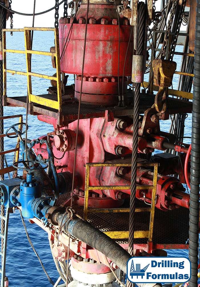
The Blow Out Preventer or BOP Stack. The Driller’s BOP control panel. The BOP operating unit- accumulator. The choke manifold. The choke control panel. The mud-gas separator. The flare line and flare pit. The trip tank and drill string valves. From this BOP control panel, the driller opens and closes, or controls, the blow out preventers and the line to the choke manifold. Rig builders usually place the control panel on the rig floor, close to the driller’s positon. Levers and switches allow the driller to quickly open and close the preventers and other valves in the system. The accumulator bottles store or accumulate hydraulic fluid under very high pressure up to 3,000 psi(over 20,000 kilo pascal). This high pressure fluid ensures that the preventers close very fast. The BOP operating unit accumulator is installed some distance from the rig floor. When the driller activates the BOP operating unit, it pumps the hydraulic fluid through the high pressure pipes, or lines, into the BOP stack. The hydraulic pressure opens or closes the preventers. Usually, the driller operates the accumulator from the control panel on the rig floor. In an emergency however, crew members can operate the BOPs by using the control valves on the accumulator itself.
Here’s a choke manifold. Flow gets to it from the BOP stack via a choke line. The manifold usually has two special valves in it called the chokes. Usually well flow goes through only one of the chokes.
The others are backups or used under special conditions. By adjusting the size of the opening of the choke, making the opening smaller or larger, the driller adjusts the amount of flow through the choke. The smaller the opening, the less flow. The larger the opening, the more flow. The less flow, the more bank pressure on the well. The more flow, the less bank pressure on the well. This adjustment of bank pressure keeps the pressure on the bottom of the flow constant, so that no more kick fluids can enter the well. The driller or another crew member uses the choke control panel to adjust the size of the choke’s opening as kick fluids flow through it. By watching the pressure on the drill pipe encasing, and by keeping the mudbomb at a constant speed, the choke operator can adjust the choke to keep the pressure on the bottom of the hole constant.
The choke operator must keep the bottom hole pressure constant to successfully control and circulate a kick out of the hole. Often, kick fluids and mud from the choke manifold go through a line to a mud-gas separator. Frequently, formation gas is the main part of a kick. However, kick fluids may also contain water, oil, or a combination of these fluids. In any case, the mud-gas separator removes the gas from the mud. With the gas removed, the pump circulates gas-free mud into the mud tanks, and back down the hole. The separated gas goes to a flare line.
In the separator, mud, with gas in it from the choke manifold, enters the top and falls over several baffle plates. The gas breaks out of the mud as it falls over the baffle plates and goes into the flare line. The gas-free mud flows into the bottom outlet, where it goes to the mud tanks for circulation down hole. The flare line conducts gas from the mud-gas separator to the flare pit on land rigs. The gas is burned, or flared, at the flare pit. Notice that the flare line outlet is a good distance away from the rig floor; so even while gas is flaring, the crew can safely work on the rig floor.
Offshore, where there is no flare pit, the flare line conducts the gas over the side of the rig. The line runs over the water a safe distance away from the rig. A trip tank is a special mud tank. It is used when they pull drill string from the hole; for example, to change out a dull bit. They also use a trip tank when they run drill string back into the hole. Pulling the drill string and running it back in is called a trip, which is why they call this small tank a trip tank. They use it to keep accurate track of how much mud the drill string displaces in the hole. When the crew pulls drill string from the hole, the mud level in the hole drops. If they let the mud level drop too far, it won’t exert enough pressure to keep formation fluids from entering the hole.
So, as the crew pulls pipe, they continually circulate fluid from the trip tank to replace the drill string and keep the hole full. They also watch for unusual changes, and they make sure that the volume of mud they put in exactly replaces the volume occupied by the drill string. Since the volumes are small, the level of mud in the trip tank is calculated in small increments, such as stands of pipe or barrels, or liters of mud, or both. If the volume they put at is less than the volume occupied by the drill string they removed, then it’s likely that formation fluids have entered the hole. For example, let’s say the crew pulls one stand of drill pipe. In this instance, the stand displaces .7 barrels or 111 liters. Therefore, they should pump .7 barrels, or 111 liters, of mud to replace the stand. The mud level in the trip tank should show a drop of .7 barrels or 111 liters. If the level in the tank shows less, then formation fluids have entered the hole, and the crew must take steps to control the well.


Design Factors Relating To Properly Design The Right Size of Mud Gas Separator for Drilling Rig

$
0
0

A mud gas separator or poor boy degasser or gas buster is one of the most critical well control equipment on drilling rigs. It is used to separate gas kick from drilling mud while circulating kick out of wells or circulating gas while drilling or workover operations. The mud gas separator used on drilling rigs is typically a vertical cylindrical vessel with many baffle plates inside because vertical vessels have small footprints. The drilling mud from the well goes into the mud gas separator and hits baffles. Then gas will be removed due to hitting action. The gas will go up and exist to atmosphere via a vent line at the top of the vessel. The drilling fluid drops after colliding baffles and exists the mud gas separator through the line and return to a mud pit.

Many-factors-are-involved-to-properly-size-mud-gas-separator

Normally, hydrostatic pressure provided by mud leg or mud seal is the maximum allowable pressure in the MSG. Operating over the mud leg pressure will result in a blow-through situation which is the situation when gas from the drilling mud going through mud leg and returning back to the rig. This maximum operating pressure depends of fluid density in the MSG but normally the pressure is below 15 psis (1 bar). The friction pressure of gas flowing through the vent line must be less than pressure from the mud leg.

There are several factors that you need to consider when designing a proper size MGS for a drilling rig.

Kick volume – For the design purpose, gas volume is used for determining the size of MSG. Proper assumption of allowable gas kick volume is needed.

Mud leg height – The minimum mud leg height is determined by the vent line friction pressure and drilling mud density expected to see during well kill operation. Typically, oil density is used to determine the mud leg height because it is a worst-case scenario.

Vent line friction – size and shape of vent line affects the friction. There are several methods to determine friction of gas flowing through vent line.

Kill rate – The kill rate is required to determine gas flow rate through the MGS and it relates to the gas flow rate through MSG. More kill rate = more gas flow rate.

For full detailed calculation, you can find out from this SPE No. 20430 – Mud Gas Separator Sizing MacDougall.

What will be occurred if improper size of MGS is used?

  • Unable to handle gas at a planned kill weight and gas will go back to the rigs.
  • In order to control excessive gas because you cannot handle with MGS, the well must be choked back and it will result in high back pressure. With additional back pressure, the formation or casing shoe can be broken.
  • The vessel and vent line can be damaged due to excessive flow.


Bullheading Calculation Example

$
0
0

Bullheading is one of the well control methods that involve pumping formation fluids back into formation into a shut-in well. You can read the basic details about bullheading from this link  http://www.drillingformulas.com/bullheading-well-control-method/. For this time, this article will be focused on a calculation example for bullheading operation.

Bull-Heading-Calculation

Components of Pumping Pressure

For the bullheading operation, pumping pressure on surface is equal to summation of all frictional pressure and formation pressure minus hydrostatic pressure (Figure 1). The equation below shows this relationship in a mathematical term.

Pump Pressure = Friction Pressure of Surface Lines + Friction Pressure of Tubing + Friction Pressure Across Perforations + Formation Pressure – Hydrostatic Pressure of Tubing

The pump pressure concept will be utilized for the bull heading calculation.

 47 Bullheading Calculation-1-01

Figure 1 – Pump Pressure Components

The well information is give below;

Production casing was set at 12,000’MD/12,000’TVD.

Bottom of perforation is at 11,500’MD/11,500’TVD.

Bottom of perforation is at 11,000’MD/11,000’TVD.

End of production tubing is at 11,500’MD/11,500’TVD.

Production packer is at 10,300’MD/10,300’TVD.

Formation fracture gradient is 0.645 psi/ft

Formation pressure gradient is 0.445 psi/ft

Shut in tubing pressure = 2,800 psi

Production casing: 7” OD, 29 ppf, L-80, capacity factor = 0.0371 bbl/ft

Production tubing: 3.5” OD, 9.2ppf, L-80, capacity factor = 0.0087 bbl/ft

Pump output (bbl/stk) = 0.1 bbl/stk

Figure 2 describes the wellbore diagram based on the given information.

47 Bullheading Calculation-1-02

Figure 2 – Diagram of the well

Calculations

For the bull heading calculation, reference points for calculation formation pressure, fracture pressure, kill weight mud are based on top of perforation because it gives the most conservative fracture pressure value.

Formation Pressure (psi) = Pressure Gradient (psi/ft) x Top of Perforation TVD (ft)

Formation Pressure (psi) = 0.445 x 11,000 = 4,895 psi

Fracture Pressure (psi) = Fracture Gradient (psi/ft) x Top of Perforation TVD (ft)

Fracture Pressure (psi) = 0.645 x 11,000 = 7,095 psi

Initial Hydrostatic Pressure (psi) = Formation Pressure (psi) – Shut In Tubing Head Pressure (psi)

Initial Hydrostatic Pressure (psi) = 4,895 – 2,800 = 2,095 psi

Initial Average Fluid Density (ppg) = Initial Hydrostatic Pressure (psi) ÷ (0.052 x Top of Perforation TVD (ft))

Initial Average Fluid Density (ppg) = 2,095 ÷ (0.052 x 11,000) = 3.66 ppg

Kill Weight Mud (ppg) = Initial Average Fluid Density + (Shut In Tubing Pressure (psi) ÷ 0.052 ÷ Top of Perforation TVD (ft))

Kill Weight Mud (ppg) = 3.66 + (2800÷ 0.052 ÷11,000) = 8.6 ppg

Maximum Initial Surface Pressure (psi) = Formation Fracture Pressure (psi) –Initial Hydrostatic Pressure (psi)

Maximum Initial Surface Pressure (psi) = 7,095 – 2,095 = 5,000 psi

The below calculation relates to pressure while bullheading.

Maximum End of Tubing Pressure (psi) = Fracture Pressure (psi) – (Kill Weight Mud (ppg) x 0.052 x End of Tubing TVD (ft)) – Initial Average Fluid Density (ppg) x 0.052 x (Top of Perforation TVD (ft) – End of Tubing TVD (ft))

Maximum End of Tubing Pressure (psi) = 7,095 – (8.6 x 0.052 x 10,500) – (3.66 x 0.052 x (11,000 – 10,500)) = 2,304 psi

Maximum pressure when Kill Mud Weight reaches perforation

@ Top of Perforation (11,000 ft TVD)

Maximum Final Pressure (psi) = Formation Fracture Pressure @ top of perforation (psi) – (Kill Weight Mud (ppg) x 0.052 x Top of Perforation TVD (ft))

Maximum Final Pressure (psi) = 0.645 x 11,000 – (8.6 x 0.052 x 11,000)

Maximum Final Pressure (psi) = 2,176 psi


@ Bottom of Perforation (11,500 ft TVD)

Maximum Final Pressure (psi) = Formation Fracture Pressure @ bottom of perforation (psi) – (Kill Weight Mud (ppg) x 0.052 x Bottom of Perforation TVD (ft))

Maximum Final Pressure (psi) = 0.645 x 11,500 – (8.6 x 0.052 x 11,500)

Maximum Final Pressure (psi) = 2,275 psi

The most conservative figure for the maximum final pressure is 2,176 psi.

As you can see, the figure reference to the top of perforation gives the most conservative figure. This is the reason why top of perforation is selected for the calculation.

Volume Pumped in Tubing (bbl) = Tubing Capacity Factor (bbl/ft) x Length of Tubing (ft)

Volume Pumped in Tubing (bbl) = 0.0087 x 10,500 = 91.4 bbl

Stroke Pumped in Tubing (stk) = Volume Pumped in Tubing (bbl) ÷ Pump Output (bbl/strk)

Volume Pumped in Tubing (stk) = 91.4 ÷ 0.1 = 914 strokes

Volume Pumped From End of Tubing to Top of Perforation (bbl) = Casing Capacity Factor (bbl/ft) x (Top of Perforation TVD (ft) –End of Tubing TVD (ft))

Volume Pumped in Tubing (bbl) = 0.0317 x (11,000 – 10,500) = 18.6 bbl

Stroke Pumped From End of Tubing to Top of Perforation (stk) = Volume Pumped in Casing (bbl) ÷ Pump Output (bbl/strk)

Volume Pumped in Tubing (stk) = 18.6 ÷ 0.1 = 186 strokes

Volume Pumped From Top of Perforation to End of Perforation (bbl) = Casing Capacity Factor (bbl/ft) x (End of Perforation TVD (ft) – Top of Perforation TVD (ft))

Volume Pumped in Tubing (bbl) = 0.0317 x (11,500 – 11,000) = 18.6 bbl

Stroke Pumped From Top of Perforation to End of Perforation (bbl)) = Volume Pumped in Casing (bbl) ÷ Pump Output (bbl/strk)

Volume Pumped in Tubing (stk) = 18.6 ÷ 0.1 = 186 strokes

Total Volume Pumped Summary

Table for volume summay

In order to push all formation fluid back to formation, it is required that the pumping volume must be at least volume from surface to end of perforation.

Pressure Schedule While Bull Heading

This is the same concept as pressure schedule in wait and weight well control method.

Pressure Decreasing in Tubing (psi/required stks) = (Maximum Initial Surface Pressure (psi) – Maximum End of Tubing Pressure (psi)) X Required strokes (stks) ÷ Tubing volume (stk)

For this calculation, 100-strokes is selected.

Pressure Decreasing in Tubing (psi/required stks) = (5,000 – 2,304) x 100 ÷ 914 = 295 psi / 100 stks

Pressure Decreasing in Casing (psi/required stks) = (Maximum Initial End of Tubing Pressure (psi) – Maximum Final Pressure (psi)) X Required strokes (stks) ÷  Volume from End of Tubing to Top of Perforation (stk)

Pressure Decreasing in Casing (psi/required stks) = (2,304 – 2,176) X 100 ÷ 186 = 96psi / 100 stks

Draw the bullhead chart based on this data

The red line is the maximum pressure. If pressure exceeds the red line, a formation will be broken down (fracture zone). The blue line represents a shut in condition. Pressure below the blue line means that the well is in an underbalanced condition (flow zone). The area between the red line and blue line is the safe zone for bullheading operation (Figure 3).

47-Bullheading-Calculation-1-03

Figure 3 – Bullheading Chart

For safe operation, pumping pressure must be within the bullheading zone (Figure 4).

47-Bullheading-Calculation-1-04

Figure 4 – Safe Bullheading


The formations may be fractured if pumping pressure exceeds the fracture line (Figure 5).

47-Bullheading-Calculation-1-05

Figure 5 -Bullheading Operation Exceeding Fracture Pressure

 Note: this chart is constructed without accounting for friction pressure. It is the most conservative pressure to prevent fracturing formation.

Reference books: Well Control Books

Well Flowing After Disconnecting The Wireline Lubricator – Well Control Situation

$
0
0

Please watch the footage below. It was a flow back after breaking out the lubricator on the rig floor.

We don’t know full details what was happened but from what we’ve seen in this VDO, it shown that the well was flowing after the wireline operation was completed. The crew broke out the connection between the wireline lubricator and the string set on the rotary table.  Few seconds after the connection was removed, the well flowed back. The flow became stronger as you can see the drilling fluid was pushed out from the drillstring quickly and the rotary table started to turn black. The lubricator was pushed by hydraulic power from the mud and it was swung around. Eventually, the crew went back to connect the lubricator to the string and the well stopped flowing.  It seem like the situation was under control at the end. Luckily, there was no gas or any spark that can cause fire on the rig floor.

What Could be Done Better?

flow-back-2

These are some key learning points that we can learn from this VDO.

  • A Full Opening Safety Valve (FOSV) should be installed on top of the string. If the well is flowing, the crew shut the well in by closing the FOSV. The risks to the crew will be greatly reduced.
  • Under estimation of formation pressure and wellbore hydrostatic pressure. Pore pressure greater than hydrostatic pressure will create an underbalanced condition.
  • Contingency well control plan should be in place prior to performing the operation. This VDO shown that there was no plan to handle the unexpected well control situation. Typically, if this case is happened, the crew should be ready to stab the FOSV so as to shut the well in.
  • Ensure the connection of FOSV is the same connection as the tubular otherwise a cross over must be prepared.

What Are Your Thought about This Case?

We would like to hear from your experience so please feel free to share your thought with us.


Hole Monitoring Procedures While Drilling or Milling Operation

$
0
0

This is the example of hole monitoring procedure while drilling or milling and this will give you some ideas only. You need to adjust it to suit with your operation

Hole-Monitoring-Procedures-While-Drilling-or-Milling-Operation

  • Perform pre-job safety meeting with personnel involved in operation.
  • The Driller or the toolpusher on the break is responsible for monitoring a well condition and identifying when a well must be shut-in with safe and correct practices.
  • If the driller sees a hole problem, the drilling operation must be stopped and inform the following people: Toolpusher, Senior Toolpusher and Company Representative.
  • Shut In Procedure While Drilling or Milling for Well Control Situation must be posted in the driller cabin where the driller can see it easily at all time.
    • Note: shut in procedure depends on requirement on each company.

  • The Driller has a responsibility to check all well control equipment and record into the sheet at the beginning of tour.
  • The Driller must review the schematic for line up and ensure the correct line up for required operation.
  • A drilling parameter trend sheet will be updated every hour during drilling operations. The parameters are as follows; RPM, active pit volume, % return flow, Rate Of Penetration (ROP), drilling torque, off bottom torque, pickup weight / slack-off weight, mud density, gas units or percentages, pumping pressure, Equivalent Circulating Density (ECD), etc.
  • The driller must monitor any drilling break and inform Toolpusher and Customer Representative if there is drilling break.
  • Kick detection devices as flow show, Pit Volume Totalizer monitor, and alarm must be tested properly and regularly.
  • Mud logger kick detection devices must also tested in the same way as rig instrumentation to confirm an accuracy and readiness.
  • Set the PVT gain/loss and the flow show at required level.
  • Discuss with pump man, shaker man, centrifuge engineer and mud engineer to have a proper communication prior to transferring any drilling fluid. Driller and mud logger must be informed prior to making any changes in the mud pit level. Any changes in centrifuge parameters must be also informed a driller and a mud logger.
  • A full opening safety valve and a closing handle with correction bottom connections that fit with of drill string which is being used must be available on the drill floor at all time. It must leave in an opened position. Driller must check this equipment.
  • The driller must confirm a current space out diagram and ensure the correct height.
  • Monitor drilling mud properties and ensure that personnel involving in drilling fluid as mud engineer, pump man, shaker man and centrifuge engineer to communicate to the drilling if there is any changes in mud properties, especially mud weight.
  • Discuss with shaker man to closely monitor cuttings over the shale shakers. If excessive cuttings and/or change in casing size/shape are observed, inform the Driller, Toolpusher and Customer Representative. It is a possible well control indicator.
  • If one of the positive well control indicators is seen, the driller must shut the well in as per a shut in procedure. Then inform Toolpusher, senior Toolpusher and Customer Representative.
  • If one of the possible well control indicators is seen, the driller must stop drilling and flow check the well. Then inform Toolpusher, senior Toolpusher and Customer Representative.
  • If there is any doubt in the well condition, the driller has the right to shut the well in. Then inform Toolpusher, senior Toolpusher and Customer Representative. Do not try to contact any supervisors first.


Hole Monitoring Procedures While Tripping

$
0
0

This is the example of hole monitoring procedure while tripping and this will give you some ideas only. You need to adjust it to suit with your operation

hole-monitoring-while-tripping

  • Perform pre-job safety meeting with personnel involved in operation.

  • Ensure a trip tank is clean without any barite sag or solid that can cause a trip tank pump failure.
  • Trip sheet must be prepared with correct drill string/ tubular displacement.
  • A Full Opening Safety Valve (FOSV) and a closing handle with correction bottom connections that fit with of drill string which is being used must be available on the drill floor at all time. Driller must check this equipment. It must leave in an opened position. It may be required to have cross over from FOSV to drill string connection.
  • The Driller is responsible for well monitoring while tripping. The driller has the right to shut the well in if there is an indicator of well control or any doubt while tripping out.
  • Shut In Procedure While Tripping for Well Control Situation must be posted in the driller cabin where the driller can see it easily at all time.
    • Note: shut in procedure depends on requirement on each company.
  • Kick detection devices as flow show, Pit Volume Totalizer monitor, and alarm must be tested properly and regularly.
  • Mud logger kick detection devices must also tested in the same way as rig instrumentation to confirm an accuracy and readiness.
  • Set the trip tank gain/loss and the flow show at required level.
  • Track volume displacement with two separate systems if possible (one from the rig system and another one from mud logger system).
  • Verify all well control equipment is properly lined up to shut the well in.
  • Confirm the correct line up for well monitoring via a trip tank.
  • Confirm the correct line up from mud pumps to the rig floor.
  • Review shut in procedure while tripping.
  • At the following events, flow checks must be performed;
  • At the bottom of the well prior to tripping out.
    • At the deepest casing shoe.
    • Anytime that there is any doubt in the well condition.
    • Anytime that the hole displacement is not correct.
    • Prior to pulling HWDP or Drill Collars through the BOPs.
    • If the monitoring or circulating system does not work properly.
    • Review any foreseeable issues with Toolpusher and Customer Representative
  • Check and maintain accurate pipe tally
  • Do not trip when filling up a trip tank
  • Perform trip drill with crew every trip if possible
  • Toolpusher should be on rig floor for at least first 10 stands to monitor the operation.
  • Trip sheets must be recorded every stand of drill pipe pulled. Assistant Driller has a responsibility to accurately fill a trip sheet while tripping.
  • Trip sheets must be kept in a tool pusher office after tripping operation completed.
  • While tripping, if the volume discrepancy is seen, Assistant Driller must inform Driller, Tool Pusher and Company Representative. The tripping operation must be stopped for further evaluation and a Full Open Safety Valve must be installed.
  • Ensure shut in while tripping procedure is posted on the rig floor closed to the driller console
  • Record pick up weight and maintain a trend in a data sheet to observe any hole issue.
  • Do not attempt to pull if you see abnormal drag 30 Klb over a current pick up weight.
  • Any abnormal dram must be informed to Toolpusher and Customer Representative.
  • If a slug is planned to pump, driller must determine volume gain from slug. The calculations can be seen from these link

Barrels of slug required for desired length of dry pipe

Weight of slug required for desired length of dry pipe with set volume of slug

  • The U-Tube effect must be discussed with team prior to pumping slug.
  • Ensure the well condition before pumping slug. Inform Toolpusher and Customer Representative before pumping slug.


  • After pumping slug, it is required to wait until the well is stable prior to continuing the tripping operation.

Deepwater Horizon Investigation Reports

$
0
0

Deepwater Horizon is one of the worst well control incidents in oil and gas industry and this situation results in losing of life and damaging environment. Therefore, it is worth to learn from this accident. In this article, we would like to share a couple of investigation reports from reliable sources for you to read and learn from this incident.

Deepwater Horizon Accident Investigation Report

Figure 1 Deepwater Horizon Accident Investigation Report from BP

Figure 1 – Deepwater Horizon Accident Investigation Report from BP

This is the report from BP internal investigation team showing all details from BP point of view and the contents are as follows;

  • Scope of Investigation
  • The Macondo Well
  • Chronology of the Accident
  • Overview of Deepwater Horizon Accident Analyses
  • Deepwater Horizon Accident Analyses
  • Investigation Recommendations
  • Work that the Investigation Team was Unable to Conduct

The report here – http://www.bp.com/content/dam/bp/pdf/gulf-of-mexico/Deepwater_Horizon_Accident_Investigation_Report.pdf

In this report, there are a lot of illustrations assisting you to understand all details.

Figure 2 - Well Schematic

Figure 2 – Well Schematic

Figure 3 - BOP Diagram (Prior and Post Accident)

Figure 3 – BOP Diagram (Prior and Post Accident)

Final Report on the Investigation of the Macondo Well Blowout

The Deepwater Horizon Study Group (DHSG) was formed by members of the Center for Catastrophic Risk Management (CCRM) in May 2010 in response to the blowout of the Macondo well on April 20, 2010. This is another report and it might give you some different ideas about this accident.

Figure 4 - Final Report on the Investigation of the Macondo Well Blowout

Figure 4 – Final Report on the Investigation of the Macondo Well Blowout

There are some highlighted subjects as listed below;

Chapter 1 – Timeline to Disaster

The Marianas

The Deepwater Horizon

The Blowout

Post Blowout Shutdown Attempts

Chapter 2 – Analysis of the Blowout

Summary of Factors Leading to Blowout

Candidate Flow Paths to the Rig Floor

Phase 1 – Production Casing Design & Construction

Phase 2 – Temporary Abandonment

Phase 3 – Attempts to Control the Well

Chapter 3 – Insights

Introduction

Organizational Accidents Perspectives

Production versus Protection Insights

Chapter 4 – Going Forward

Introduction

Observations

Findings

Commentary

Recommendations

These are some images in this report.

Figure 5 – Location of Macondo Well

Figure 5 – Location of Macondo Well

Figure 6 Wellbore Schematic Comparison

Figure 6  Wellbore Schematic Comparison

The report here –  http://ccrm.berkeley.edu/pdfs_papers/bea_pdfs/dhsgfinalreport-march2011-tag.pdf

We wish these two important reports would be advantageous to you. Well control is one of the most critical part of drilling engineering and operation.

Hole Monitoring Procedures While Running Casing or Tubing

$
0
0

This is the example of hole monitoring procedure while running casing and this will give you some ideas only. You need to adjust it to suit with your operation.

hole monitoring while running casing

  • Perform pre-job safety meeting with personnel involved in operation.
  • A Full Opening Safety Valve (FOSV) and a closing handle with correction bottom connections that fit with of drill string which is being used must be available on the drill floor at all time. Driller must check this equipment. It must leave in an opened position. It may be required to have cross over from FOSV to casing connection.
  • The Driller is responsible for well monitoring while tripping. The driller has the right to shut the well in if there is an indicator of well control or any doubt while tripping out.
  • Trip sheet must be prepared with correct drill string/ tubular displacement.
  • The Driller is responsible for well monitoring while tripping. The driller has the right to shut the well in if there is an indicator of well control or any doubt while running casing or tubing.
  • Shut In Procedure Running Casing or Tubing for Well Control Situation must be posted in the driller cabin where the driller can see it easily at all time.
    • Note: shut in procedure depends on requirement on each company.
  • Kick detection devices as flow show, Pit Volume Totalizer monitor, and alarm must be tested properly and regularly.
  • Mud logger kick detection devices must also tested in the same way as rig instrumentation to confirm an accuracy and readiness.
  • Set the trip tank gain/loss and the flow show at required level.
  • Use mud pit to monitor the well if larger casing is ran. Use a trip tank to monitor the well if a smaller casing or tubing is ran. This depends on the rig system.
  • Track volume displacement with two separate systems if possible (one from the rig system and another one from mud logger system).
  • Verify all well control equipment is properly lined up to shut the well in.
  • Confirm the correct line up for well monitoring via a trip tank.
  • Confirm the correct line up from mud pumps to the rig floor.
  • Review shut in procedure while running casing or tubing.
  • Review any foreseeable issues with Toolpusher and Customer Representative
  • Ensure correct casing or tubing tally while running in hole
  • Trip sheets must be recorded every stand of casing / tubing ran. Assistant Driller has a responsibility to accurately fill a trip sheet while running casing/tubing.
  • Trip sheets must be kept in a tool pusher office after tripping operation completed.
  • While running casing/tubing, if the volume discrepancy is seen, Assistant Driller must inform Driller, Tool Pusher and Company Representative. The running casing/tubing operation must be stopped for further evaluation and a Full Open Safety Valve must be installed.
  • Ensure shut in while running casing/tubing procedure is posted on the rig floor closed to the driller console
  • While tripping, if the volume discrepancy is seen, Assistant Driller must inform Driller, Tool Pusher and Company Representative. The tripping operation must be stopped for further evaluation and a Full Open Safety Valve must be installed.


Well Control Procedure for Non-Shearable String

$
0
0

There are many cases when non-shearable string is across the BOP therefore blind shear rams will not be able to shear the string to secure the well if needed. The special procedure must be in place to deal with this situation. This is an example of well control procedure for non-shearable string. If you want to use it for your rig, it must be modified to match with your rig operation.

Well Control Procedure for Non-Shearable String FB

  • Define which equipment is unable to be sheared such as BHA, thick wall drill collar, testing tool, downhole pump, etc. This step should be done ahead of the time.
  • Perform pre-job safety meeting with personnel involved in operation.
  • Before pulling out non-shearable string through BOP, flow check must be conducted to ensure a well condition.
  • Driller must ensure well static before pulling out.
  • Driller must ensure all line up for shut line is correct.
  • Shut in criteria if the well control indicator is seen.
    • If the risk is acceptable, pull the string out of the hole and shut the well in using blind or blind/shear rams. If this method is not applicable, another option is to make up a shearable string as drill pipe and run in hole. Then shut the well in using annular preventor or rams preventor.
    • If the risk is not acceptable, stab full opening safety valve and shut the well in via annular preventor. It might be possible to close rams if size of rams match with the non-shearable string. Driller must ensure the correct space out to prevent closing the BOP (annular or rams) on non-slick surface.

These procedures will be followed if the well is unable to be secured from the steps above.

Drop Drillstring During Tripping Operation

  • Lower the string close to the rotary table
  • Close Annular Preventer
  • Tie a rope on the elevator latch
  • Lower the block and takes the weight off the elevator.
  • Pull the rope to unlatch the elevator
  • Open Annular Preventer to drop the string
  • Shut the well in via blind/blind-shear rams

Drop Drillstring If The String Is Made Up To Top Drive

  • Lower the string close to the rotary table
  • Set slips and break the connection at top drive for one turn
  • Pick up and remove slips
  • Close Annular Preventer
  • Break out the top connection as fast as you can until the string is sceptered from top drive.
  • Open Annular Preventer to drop the string
  • Shut the well in via blind/blind-shear rams

Volumetric Well Control Example Calculations

$
0
0

This example demonstrates the calculations and the steps of the volumetric well control which will help you understand about what calculations according to the volumetric procedures.

volumetric Calculation FB cover

Gas kick at the bottom but unable to circulate due to drillstring plugged off. The well control information is listed below;

  • Pit gain = 10 bbl
  • Shut in Drill Pipe Pressure = 0 psi (drillstring plugged)
  • Shut in Casing Pressure = 400 psi
  • Current mud weight = 11.0 ppg
  • Casing shoe depth = 6,000’MD/6,000’TVD
  • Hole TD = 9,000’MD/9,000’TVD
  • Hole size = 12.25”
  • Casing ID = 12.5”
  • Drill pipe size = 5”, 19 ppf
  • BHA consists of 6.5” drill collar
  • Length of BHA = 800 ft
  • Average pipe per stand = 94 ft

Basic RGB

Figure 1 – Well Information

The volumetric well control will be utilized in order to bring gas up to surface while maintaining bottom hole pressure almost constant.

Safety Factor and Pressure Increment are 100 psi.

Assumption: Gas kick at the bottom

Mud Increment

Mud Increment (MI) is calculated by the following equation

MI equation


Where;

MI = Mud Increment (MI), bbl

PI = Pressure Increment (PI), psi

ACF = annular capacity factor between casing and drillstring, bbl/ft

MW = mud weight, ppg

ACF = (12.52 – 52) ÷ 1029.4 = 0.1275 bbl/ft

MI equation 2


Mud Increment (MI) = 22.3 bbl

Volumetric Control Procedures

  1. We determine the Safety Factor (SF), Pressure Increment (PI) and Mud Increment (MI).
    • Safety Factor (SF) = 100 psi
    • Pressure Increment (PI) = 100 psi
    • Mud Increment (MI) = 100 psi
  2. Wait for casing pressure to increase by Safety Factor (SF) + Mud Increment (MI). For this case, we will wait until casing pressure reaches 600 psi (400 + 200). At this point, the over balance is 200 psi and gas migrates up from the bottom of the well.

Figure 2 - Allow Casing To Increase by SF + PI

Figure 2 – Allow Casing To Increase by SF + PI

Basic RGB

Figure 3 – Diagram Showing Gas Migration and Casing Pressure Increases

  1. Hold casing pressure constant and bleed off fluid volume by Mud Increment (MI). For this case, the volume of mud bled off is equal to 22.3 bbl. At this point, the over balance will be 100 psi.

Figure 4 - Bleed of Mud Volume by MI

Figure 4 – Bleed of Mud Volume by MI

Basic RGB

Figure 5 – Diagram Showing Bleeding off Mud Volume by Mud Increment (MI) Holding Casing Pressure Constant

  1. Shut the well in and wait until casing pressure increases by Pressure Increment (PI). At this point, casing pressure will increase to 700 psi and the overbalance of the wellbore is 200 psi.

Figure 6 - Allow Casing Pressure to Increase by Pressure Increment (PI)

Figure 6 – Allow Casing Pressure to Increase by Pressure Increment (PI)

Basic RGB

Figure 7 – Diagram Showing Gas Migration and Casing Pressure Increases

  1. Repeat step#3 and step#4 until gas at surface (casing pressure stops increasing) or the well kill operation can be performed with an alternative method. For example, if the pumps fails and the volumetric well control method is selected because you don’t want the bottom hole pressure increase too much. When the pumps are back in a service, other well control methods as driller’s method or wait & weight can be performed. As per this example, we will perform the volumetric well control until gas at surface.

Figure 8 – Table Demonstrates Steps of Volumetric Well Control

Figure 8 – Table Demonstrates Steps of Volumetric Well Control

Referring to Figure 8, you can see that casing pressure is allowed to increase and the mud is bled off to compensate increase in bottom hole pressure. Figure 9 is a summary chart showing casing pressure and over balance during the volumetric operation. The overbalance of the well bore is maintained between 100 psi to 200 psi. In some situations when there is a chance to break formation at a casing shoe, you might consider selecting the lower figure of safety factor as 50 psi.

Figure 9 - Pressure Summary

Figure 9 – Pressure Summary

Reference books: Well Control Books

Lubricate and Bleed Example Calculations

$
0
0

This example demonstrates the calculations and the steps of lubricate and bleed which will help you understand about what calculations according to lubricate and bleed procedures.

Example of Lubricate and Bleed Well Control Calculation

Gas kick migrates to surface underneath the BOP safely via Volumetric Well Control. The circulation is not possible due to drillstring plugged off therefore the decision is made to perform Lubricate and Bleed to kill the well. The well control information is listed below;

  • Shut in Drill Pipe Pressure = 0 psi (drillstring plugged)
  • Shut in Casing Pressure = 1,000 psi without any safety factor
  • Gas on surface at the BOP
  • Current mud weight = 11.0 ppg
  • Casing shoe depth = 6,000’MD/6,000’TVD
  • Hole TD = 9,000’MD/9,000’TVD
  • Hole size = 12.25”
  • Casing ID = 12.5”
  • Drill pipe size = 5”, 19 ppf
  • BHA consists of 6.5” drill collar
  • Length of BHA = 800 ft
  • Average pipe per stand = 94 ft
  • Wellhed rating = 5000 psi
  • BOP rating = 10,000 psi
  • Leak off pressure at shoe = 16.0 ppg
  • Estimated gas volume at BOP = 70 bbl
  • Estimated Bottom of gas = 549 ft

53 Example of Volumetric Well Control Calculation

Figure 1 – Well Information

Note: Before going onto detailed calculations, it is very important to explain to you that the Lubricate and Bleed method can kill the well or just reduce surface pressure. It is not 100% every time that the well will be successfully killed and you will see in the detailed calculations later.

The concept of Lubricate and Bleed is to remove gas at surface when the circulation cannot be performed. With this method, bottom hole pressure will be almost constant.  The mud will be pumped in to the well to increase bottom hole pressure and later gas will be bled off to compensate what hydrostatic pressure added into the system.

Lubricate and Bleed Calculations

Select Safety Factor (SF) – it is recommended to use a small and practical safety factor. For this calculation, the Safety Factor is 50 psi.

Select Pressure Increment (PI) – this is the hydrostatic of mud which is planned to lubricate into the well. Pressure Increment (PI) should be a small and practical figure so Pressure Increment (PI) for this calculation is 50 psi.

Calculate Lube Increment (LI)

Lube Increment (LI)is calculated by the following equation

LI calculation

Where;

LI = Lube Increment (MI), bbl

PI = Pressure Increment (PI), psi

ACF = annular capacity factor between casing and drillstring, bbl/ft, at surface.

ACF = (12.52 – 52) ÷ 1029.4 = 0.1275 bbl/ft

MW = mud weight, ppg

For this example, 14-ppg mud will be used.

** It is suggested to use higher mud weight as practical as possible. The reasons are small Lube Increment (LI) and higher change to kill the well.

LI calculation

Lube Increment (MI) = 8.8 bbl

Maximum Allowable Surface Casing Pressure (MASCP)

We need to know surface limitation prior to inject otherwise it can cause failure on surface equipment or break formation downhole and for this situation, Leak Off at show (16 ppg) is the limitation. In some cases, if you work on an old well, casing rating may be a limitation so you need to check and use the lower figure. For the worst case, we assume that gas will be fully replaced with kill mud (14.0 ppg).

MASCP is calculated by the equation below;

MASCP = Leak off Pressure – Hydrostatic Pressure

Hydrostatic Pressure = Hydrostatic Pressure from Kill Mud (14 ppg) + Hydrostatic Pressure from Current Mud (11 ppg)

Hydrostatic Pressure = (0.052 × 14 × 549) + (0.052 × 14 x 5,451)

MASCP = (0.052 × 16 × 6,000) – [(0.052 × 14 × 549) + (0.052 × 14 x 5,451)]

MASCP = 4,992– 400 – 3,118

MASCP = 1474 psi

Note: We don’t calculate the MASCP with only current mud weigh because it is not the worst case scenario.

Lubricate and Bleed Steps

  1. We determine the Safety Factor (SF), Pressure Increment (PI) and Mud Increment (MI).
    • Safety Factor (SF) = 50 psi
    • Pressure Increment (PI) = 50 psi
    • Lube Increment (LI) = 8.8 bbl
  2. Lubricate mud volume equal to Lube Increment (LI)

For this step, it will add safety factor into the well; however, if surface casing pressure already has safety factor, step#2 and step#3 must be skipped in order to prevent excessive safety factor which may cause fracturing shoe.

Volume gas is compressed by lubricated mud.

Volume of gas = Volume of gas at previous condition – Lube Increment (LI)

Volume of gas = 70 – 8.8 = 61.2 bbl

Pressure of compressed gas is determined by Boyld’s Law.

P2 = (P1 × V1) ÷ V2

Where;

P1 = Pressure of gas at previous condition, psi

V1 = Volume of gas at previous condition, bbl

V2 = Volume of gas compressed by lubricated mud, bbl

P2 = Pressure of gas compressed by lubricated mud, psi

This pressure represents casing pressure due to gas compression.

P2 = (1000 × 70) ÷ 61.2 = 1,144 psi

Overbalance of bottom hole pressure

Overbalance = P2 + Hydrostatic Pressure due to Lube Increment (LI) – P1 + Safety Factor

Where;

P1 = Pressure of gas at previous condition, psi

P2 = Pressure of gas compressed by lubricated mud, psi

Hydrostatic Pressure due to Lube Increment (LI) = Pressure Increment (PI)

Safety Factor = 0 psi

Overbalance = 1,144 + 50 – 1000 + 0

Overbalance = 194 psi

Figure 2 - Table Represents Pressure and Volume of Step2

Figure 2 – Table Represents Pressure and Volume of Step#2

53 Example of Volumetric Well Control Calculation

Figure 3 – Diagram shows mud lubricated into the well

  1. Bleed gas via choke until casing pressure reach the initial pressure in step#2

This step will establish a Safety Factor (SF) because surface pressure is bleed off to the original value and the only thing that adds into the wellbore is hydrostatic pressure from Lube Increment (LI) which is 50 psi for this example.

Overbalance of bottom hole pressure

Overbalance = Current Overbalance in step#2 – (Casing Pressure after Lubricating – Casing Pressure after Bleeding off)

Overbalance = 194 – (1,144 –1,000) = 50 psi

Figure 4 - Table Represents Pressure and Volume of Step3

Figure 4 – Table Represents Pressure and Volume of Step#3

53 Example of Volumetric Well Control Calculation

Figure 5 – Diagram shows bleeding gas out of the well


  1. Lubricate mud into the well equal to Lube Increment (LI)

8.8 bbl of mud is pumped and this will give 50 psi hydrostatic pressure increment.

Gas volume will be compressed by 8.8 bbl therefore the volume of gas will be reduced from 61.2 bbl to 52.4 bbl (61.2-8.8 = 52.4).

This pressure represents casing pressure due to gas compression.

Pressure of compressed gas is determined by Boyld’s Law.

P2 = (P1 × V1) ÷ V2

Where;

P1 = Pressure of gas at previous condition, psi

V1 = Volume of gas at previous condition, bbl

V2 = Volume of gas compressed by lubricated mud, bbl

P2 = Pressure of gas compressed by lubricated mud, psi

This pressure represents casing pressure due to gas compression.

P2 = (1000 × 61.2) ÷ 52.4 = 1,168 psi

Overbalance of bottom hole pressure

Overbalance = P2 + Hydrostatic Pressure due to Lube Increment (LI) – P1 + Safety Factor

Where;

P1 = Pressure of gas at previous condition, psi

P2 = Pressure of gas compressed by lubricated mud, psi

Hydrostatic Pressure due to Lube Increment (LI) = Pressure Increment (PI)

Safety Factor = 50 psi ** The safety factor is established from step#2 and step#3.

Overbalance = 1,168 + 50 – 1000 + 50

Overbalance = 268 psi

Figure 6 - Table Represents Pressure and Volume of Step4

Figure 6 – Table Represents Pressure and Volume of Step#4

53 Example of Volumetric Well Control Calculation

Figure 7 – Diagram shows mud lubricated into the well


  1. Bleed casing pressure until casing pressure is equal to casing pressure in step#4 before lubricating minus Pressure Increment (PI)

This step will intentionally reduce casing pressure which has the same value of Pressure Increment (PI) which is 50 psi for this case.

Casing pressure @ step#4 before lubricating = 1,000 psi

PI = 50 psi

Casing pressure after bleeding off = 1000 – 50 = 950 psi

Overbalance of bottom hole pressure

Overbalance = Current Overbalance in step#4 – (Casing Pressure after Lubricating – Casing Pressure after Bleeding off)

Overbalance = 268 – (1,168 –950) = 50 psi

Figure 8 - Table Represents Pressure and Volume of Step5

Figure 8 – Table Represents Pressure and Volume Bled off of Step#5

53 Example of Volumetric Well Control Calculation

Figure 9 – Diagram shows gas bled off to planned pressure

  1. Repeat step#4 and step#5 until gas is out of the annulus (well dead) or casing pressure increase to Maximum Allowable Surface Casing Pressure (MASCP)

The table (Figure 10) shows all the required steps as per Lubricate and Bleed.

Figure 10 - Table Represents Pressure and Volume Bled off with Lubricate and Bleed

Figure 10 – Table Represents Pressure and Volume Bled off with Lubricate and Bleed

One thing that we would like to point out is at the last step the volume of gas left in hole is 8.4 bbl. Beyond this step is impossible because you need to lubricate a lubricate volume of 8.8 bbl and the casing pressure will exceed the MASCP. Therefore, the operation will stop at this point and casing pressure will be down from 1,000 psi to 750 psi with 50 psi overbalance.

Figure 11 – Not Enough Volume Gas Left in the Well to Lubricate

Figure 11 – Not Enough Volume Gas Left in the Well to Lubricate and Casing Pressure Exceeds MASCP

Thing to Remember

  • Lubricate and Bleed may or may not be able to kill the well but at least you can reduce surface casing pressure in a controlled manner.
  • Gas volume is getting smaller due to bleed off therefore it may reach the point that when you try to lubricate the mud, it will create very high surface casing pressure because of Boyle’s law. High surface pressure can cause either surface equipment damage or fracture formation at a casing shoe. It is very important to do the full step calculations in order to know when you will not be able to lubricate anymore. You need to know Maximum Allowable Surface Casing Pressure (MASCP) as your maximum lubricated pressure.

Reference books: Well Control Books

Well Control and Blow Out !!!

$
0
0

Many people ask us every time about well control but many of them understand that well control is when the rigs are burn. This is not the right concept.

blow-out-fb-vdo
Well Control is a situation when hydrostatic pressure in a wellbore is less than formation pressure therefore reservoir fluid will come into a well. If a well control situation is not taking care of properly, it will result in blow like you can see in the VDO below.

The short VDO, only 1 minute and 34 seconds, clearly show that what will be happening if the well cannot be control.

This is another example of blow out.

If you want to learn more about well control, you can find more information here
Well Control Articles

Kill The Blow Out Well Using Nuclear Bomb

$
0
0

We’ve found this VDO on Youtube and this is one of the most interesting vdo. This is about how to kill the blow out well using a nuclear bomb. We are not sure when it was happened but from what you can see, this is quite long time ago when directional technology is not good enough to successfully execute a relief well operation. Please see the vdo below and we already added vdo transcript for further learning.

Transcript for learning – How the Soviets stopped well blowouts

soviet-kill-the-well

A nuclear explosion puts out a gas-well blaze. This gas-well fire roared out of control at one of the natural gas deposits in this country. The giant torch consumed nearly 10 million cubic meters of valuable fuel a day. A full scale battle was launched against the roaring infernal.

First, an attempt was made to cool off the near shaft area by water. Jets of water cut off the flame from the gas stream. Then, part of the gas was diverted with a help of a structure directed over the well. Here, gas is being burnt at draw-offs. But it proved utterly impossible to lower piping into the well to bring it under control. There was a sudden pressure surge in the well and gas started to leak out into permeable geological strata. Dangerous amounts of hydrogen sulfate began to escape. This created a threat of air contamination over a big, populated area.

Attempts to plug the well by conventional means have all failed. Then, it was decided to choke the well by a contained underground nuclear explosion. When project materials were ready, a special digging rig was set up nearby. This was used to sink a deep shaft at an angle to the gas well. A nuclear explosion was to be set off in plastic geological material below gas impermeable strata.

When the emplacement of the charge was over, the shaft was plugged with concrete. Preparations for the blast are near in completion. Machines and equipment have all been moved to safety, 5 kilometers away from the zero area. Now the flame and the nuclear charge are left alone, face-to-face. The explosion is only seconds away. The camera films the impact of the detonation. And the gas flame beings to subside.

Let us now take a look at what has actually happened deep down below. The shock wave of the explosion, compassed the surrounding geological material and pushed it aside, blocking the flow of gas. The well was plugged by crashed rock. It took only 23 seconds to do the job. A radiation survey of the area failed to detect any activity. And unusual quire has set in. Soon, the dead well was filled in with dirt. A contained underground nuclear explosion has helped to save large quantities of valuable gas for our national economy.

Well Control

$
0
0

This page contains well control contents in this site.

well-control-in-one-page

Basic Calculation Related to Well Control

Adjusted maximum allowable shut-in casing pressure
Brine weight with temperature correction
Calculate Annular Capacity
Calculate Annular Pressure Loss
Calculate Equivalent Circulation Density (ECD) with complex engineering equations
Calculate Influx Height
Calculate inner capacity of open hole/inside cylindrical objects
Calculate Pressure Gradient and Convert Pressure Gradient
Calculate Specific Gravity (SG) in oilfield unit
Convert Pressure into Equivalent Mud Weight
Convert specific gravity to mud weight (ppg and lb/ft3) and pressure gradient (psi/ft)
Corrected D Exponent Calculation
D Exponent Calculation
Determine height of light weight spot pill to balance formation pressure
Determine the actual gas migration rate
Drill pipe pulled to lose hydrostatic pressure
Equivalent Circulating Density (ECD) in ppg
Equivalent Circulating Density (ECD) Using Yield Point for MW less than 13 ppg
Equivalent Circulating Density (ECD) Using Yield Point for MW More than 13 ppg
Estimate gas migration rate in a shut in well
Estimate Type of Influx (kick)
Formation Integrity Test (FIT) Procedure and Calculation
Formation Pressure from Kick Analysis
How does the 0.052 constant come from?
Hydraulic Horse Power (HPP) Calculation
Hydrostatic Pressure (HP) Decrease When POOH
Hydrostatic Pressure Calculation
Hydrostatic Pressure Loss Due to Gas Cut Mud
Kick Tolerance Calculation
Kill Weight Mud
Leak Off Test (Procedures and Calcuation)
Loss of Hydrostatic Pressure due to Lost Return
Maximum pit gain from gas kick in water based mud
Maximum Surface Pressure from Gas Influx in Water Based Mud
Pipe Displacement Calculation
Pump Output Calculation for Duplex Pump and Triplex Pump
Pump pressure and pump stroke relationship
Temperature Conversion Formulas

Drilling Mud Calculation (Related to Well Control)

Determine the density of oil and water mixture
Increase mud weight by adding barite
Increase Mud Weight by Adding Calcium Carbonate
Increase Mud Weight by Adding Hematite
Mixing Fluids of Different Densities with Pit Space Limitation
Reduce mud weight by dilution
Starting volume of original mud (weight up with Barite)
Starting volume of original mud (weight up with Calcium Carbonate)
Starting volume of original mud (weight up with Hematite)
Volume of mud in bbl increase due to adding barite
Volume of Mud Increases due to Adding Calcium Carbonate
Volume of Mud Increases due to Adding Hematite

Slug Calculations

Barrels of slug required for desired length of dry pipe
Weight of slug required for desired length of dry pipe with set volume of slug

Basic Knowledge Relating To Well Control

Abnormal Pressure Caused By Faulting
Abnormal Pressure from Anticline Gas Cap
Accumulator Capacity – Usable Volume per Bottle Calculation (Surface Stack)
Accumulator Capacity – Usable Volume per Bottle Calculation for Subsea BOP
Blowout – Oilfield Disaster That You Need to See
Bottom Hole Pressure Relationship
Bottom Hole Pressure with Constant Surface Pressure
Boyle’s Gas Law and Its Application in Drilling
Casing Shoe Pressure While Circulating Influx in Well Control Situation
Causes of Kick (Wellbore Influx)
Cement Transition Period in The Oil Well Can Cause Well Control Situation
Difference between True Vertical Depth (TVD) and Measured Depth (MD)
Effect of Frictional Pressure on ECD while forward circulation
Effect of Frictional Pressure on ECD while reverse circulation
Estimated mud weight required to safely drill the well
Factors Affecting Kick Tolerance
Gas Behavior and Bottom Hole Pressure in a Shut in well
Gas Behavior with Constant Bottom Hole Pressure
How Does 1029.4 Come From?
How to Predict Formation Pressure Prior to Drilling
Kick Tolerance
Kick Tolerance Concept and Calculation for Well Design
Kill Rate Selection
Kill The Blow Out Well Using Nuclear Bomb
Know about Swabbing and Well Control
Lag Time for Drilling Business and How to Calculate Theoretical Lag Time
Learn About Drill Pipe Float Valve
Learn about Maximum Surface Pressure in Well Control (MASP, MISICP and MAASP)
Let’s apply U-Tube concept
Lost circulation and well control
Maximum formation pressure that can be controlled when we shut the well in
Maximum influx height to equal the maximum allowable shut-in casing pressure
Maximum Initial Shut-In Casing Pressure (MISICP)
Pore Pressure Evaluation While Drilling Is Important For Well Control
Positive Kick (Wellbore Influx) Indications
Possible Kick (wellbore influx) Indications Part1
Possible Kick (wellbore influx) Indications Part2
Practice to drill the well at near balance condition in conjunction with well control precaution
Pressure Loss and Equivalent Circulating Density Review
Pressure Loss and Equivalent Circulating Density Review – Reverse Circulation
Review Hydrostatic Pressure and U-Tube Concept
Shut in Procedures and Their Importance
Surge Pressure, Swab Pressure and Trip Margin
Trip Margin Calculation
Understand about Friction Pressure Acting in Wellbore
Understand Hydrostatic Pressure
Understand the Formation Pressure
Understand U-Tube and Importance of U-Tube
Water Kick and Oil Kick Indications
Well Control or Blow out
What are differences between Full Opening Safety Valve (TIW valve) and Inside BOP valve (Gray Valve)?
What are differences between possible and positive well control indicators
What are the differences between FIT and LOT?
What is “Background Gas”?
What is “Connection Gas”?
What is “Drilled Gas”?
What is “Trip gas”?
What is a trip tank?
What is Flow Check?
What is Primary Well Control?
What is Secondary Well Control?
What is space out in drilling (especially in well control)?
What is Tertiary Well Control?
Why Do We Need To Minimize Influx (Kick)?
Why Was This Well Control Situation Happened?

Shut in Procedures

2 Types of Shut-In (Hard Shut In and Soft Shut In)
Determining Correction Initial Circulating Pressure
Post Shut-In Procedures while Drilling
Post Shut-In Procedures While Tripping -What data should be recorded?
Shut-In Procedure while Drilling
Shut-In Procedure while Tripping
Shut-In while Wireline Logging Operation

Surge and Swab Calculation

Determine surge and swab pressure for close-ended pipe
Determine surge and swab pressure for open-ended pipe
Determine surge and swab pressure method 2
Determine surge and swab pressure method 2 Calculation Example
Surge and Swab Calculation Method 1

Shoe Pressure While Circulating Kick

Shoe pressure when the gas kick is above a casing shoe
Understand shoe pressure – Shoe pressure when the gas kick Passing Shoe
Understand shoe pressure – Top of Gas Kick Below the Shoe

Well Control Equipment

Blow Through Situation in Mud Gas Separator (Well Control Equipment)
Design Factors Relating To Properly Design The Right Size of Mud Gas Separator for Drilling Rig
Drill string valves and IBOPs VDO Training
Mud Gas Separator (Poor Boy Degasser) Plays A Vital Role in Well Control Situation
Trip Tank and Its Importance on Well Control

Blow Out Preventer

4-Way Valve Operation in Blow Out Preventer Accumulator (Koomey) Unit
Accumulator (Koomey)
Annular Preventers
API Ring Gaskets Used in BOP Connections
Basic Understanding of Sub Sea BOP VDO Training
Blow Out Preventer (BOP) Equipment VDO Training
Blowout Preventers (BOP) VDO Training
BOP testing procedures
Calculate Bottles Required for Koomey Unit (Accumulator Unit)
Diverter Systems In Well Control
Mechanism of Accumulator (Koomey Unit)
Ram Preventers as Well Control Equipment
Reserve Fluid System and Pumping System in Koomey Unit
Understand More about Pipe Rams, Variable Bore Rams and Shear Rams
What is Closing Ratio in Blow Out Preventor (BOP)?

Driller’s Method

Advantages and Disadvantages of Driller’s Method
Bottom hole pressure change while performing well control operation with driller’s method
Circulate Kill Mud – 2nd Circulation of Driller’s Method
Circulate Out The Influx Holding Drill Pipe Pressure Constant
Driller’s Method in Well Control
Driller’s Method or Wait and Weight Method – What is The Practical Well Control Method for You?
Driller’s Method Quiz No. 1
Driller’s Method Quiz No. 2
Driller’s Method Quiz No. 3
Driller’s Method Quiz No. 4
Establish Circulation in Driller’s Method Step – 1
Float Bumping Procedures To Get Shut In Drill Pipe Pressure
How are pressure and pit volume doing during the first circulation of the driller’s method?
How is pressure doing for the second circulation of driller’s method
Lag Time and Its Importance for Well Control Operation
Shut Down And Perform Flow Check – Last Step of Drille’s Method
Shut Down Pumps and Weight Up Mud in Driller’s Method
Shut in the well and get pressure data (driller’s method)
Summary of Driller’s Method

Wait and Weight Methond (Engineering’s Method)

Advantages and Disadvantages of Wait and Weight Method
Drill Pipe Pressure Schedule Calculation for Wait and Weight Well Control Method
Formulas for Wait and Weight Well Control Method
How wait and weight method controls bottom hole pressure
Pressure Profile of Drillpipe and Casing Pressure while killing a well with wait and weight method
Slow Circulation Rate (SCR)
Wait and Weight Well Control Method (Engineer’s Method)

Volumetric Well Control

How To Perform Volumetric Well Control Method
Volumetric Well Control – When It Will Be Used
Volumetric Well Control Example Calculation

Lubricate and Bleed Well Control

Lubricate and Bleed in Well Control
Example of Lubricate and Bleed Well Control Calculation

Bullheading Well Control

Bullheading Well Control
Bullheading Calculation Example

Horizontal Wells Well Control

Introduction To Well Control for Horizontal Wells
Kick Scenarios in Horizontal Wells For Well Control
Kick Prevention for Horizontal Wells
Behavior of Gas in a Horizontal Well Kick

Deepwater Well Control

Choke Line Friction – How Does It Affect Deepwater Well Control?
Choke Line Friction Pressure as Kill Weight Mud Approaches the Surface
Fracture Gradient Reduction Due to Water Depth
Hard Shut-In Procedure while Drilling with a Subsea BOP Stack
How To Compensate Choke Line Friction For Deep Water Well Control
How To Measure Choke Line Friction (CLF) for Deepwater Well Control
Riser Margin – One of Important Concepts For Deep Water Drilling
Shut-In Procedure while Tripping with a Subsea BOP Stack

Stripping Well Control

Basic Understand of Stripping Operation Well Control with Gas Influx
Basic Understanding About Well Control With Pipe Off Bottom
Kick Penetration For Stripping Operation
Practical Considerations for Stripping Well Control Operation
Stripping Methods for Non Migration Kicks When There is an Off Bottom Well Control
Stripping Procedure with Volumetric Control For Migrating Kick
Stripping Procedure without Volumetric Control for Non-Migrating Influx
Stripping with Volumetric Control Steps and Example Calculation

Hole Monitoring Procedure

Hole Monitoring Procedures While Drilling or Milling Operation
Hole Monitoring Procedures While Running Casing
Hole Monitoring Procedures While Tripping

Ballooning in Well Control

How to Identify Well Ballooning
How to Prevent Well Ballooning
Well ballooning (wellbore breathing or micro fracture)

Useful Excel Files and Ebook

Download Wild Well Control Technical Book
Free BOP Drawing Template
Free Useful Well Control Spread Sheet – All Important Well Control Formulas For Oilfield Personnel
Trip Sheet Excel File
Well Control Kill Sheet Free Download
Well Control Tracking Sheet

Etc

Blow Out on The Rig Floor VDO
Oil Field Conversion Part 1 – Area, Circulation Rate, Impact Force
Well Control Acronyms
Well Control Formulas Part 1
Well Control Formulas Part 2
Well Control Formulas Part 3
Well Control Formulas Part 4
Well Control Formulas Part 5
Well Control Formulas Part 6
Well Control Procedure for Non-Shearable String
Well Flowing After Disconnecting The Wireline Lubricator – Well Control Situation (VDO)

IWCF Drilling Calculation Part 1 – 3 Review

$
0
0

International Well Control Forum (IWCF) has provided useful learning material, which is IWCF Drilling Calculation Part 1 – 3, to drilling people. We will review all of them and see the content inside. Additionally, these ebooks are available to download from IWCF website. Thanks for their contribution to drilling industry.

iwcf-drilling-calculation

IWCF Drilling Calculation Part 1 – Introduction to Calculations

The part 1 consist of basic mathematics that you need to know in order to work out any mathematical questions. This cover from very beginning for people who don not have a strong background in mathematics before. The content is very well written and easy to understand.  There is also the answer section which you need to use to check the anwer. The content of the first part are listed below;

Section 1 Whole Numbers
Section 2 Estimating and Rounding
Section 3 Basic mathematical calculations and the use of the calculator
Section 4 Fractions, decimals, percentages and ratios
Section 5 Units of measurement
Section 6 Mathematical symbols, equations and arithmetical operations
Section 7 Introduction to solving equations and the use of formulae
Section 8 Converting and conversion tables

A Screen Capture of Drilling Calculation Part 1 (Ref: http://www.iwcf.org/)

IWCF Drilling Calculation Part 2 – Areas and Volume

The second part is about areas and volume. For the area calculation, you will learn how to determine area and estimate area with various shapes and there are discussion about units related in areas calculation. For the volume calculation part, you will learn how to define volume and capacity, how to calculate volumes of various shapes and the application on the rig. Moreover, you will learn about pump output, stroke, time which are very important to the well control calculation. The solution of this part is also provided. The details of this section is shown below;

Section 1 Calculating areas
Section 2 Calculating volumes
Section 3 Oilfield volumes
Section 4 Borehole geometry – Surface BOP operations
Section 5 Borehole geometry – Subsea BOP operations
Section 6 Pump output, strokes, time
Section 7 Volume and pump strokes – kill sheet calculations
Section 8 Trip monitoring calculations

A Screen Capture of Drilling Calculation Part 2 (Ref: http://www.iwcf.org/)

IWCF Drilling Calculation Part 3 – Well Control

The third part will cover various concepts of well control so learner must have good basic calculation background. You will learn about hydrostatic pressure and related oilfield terminology in well control. The next part is about the circulating system on the rig. The last two parts are about introduction to well control relating to kick prevention and detection, primary well control and secondary well control. There are many examples which will help you understand the key concepts and you need to practice the calculations as well.

The details of the third part is shown below;

Section 1 Hydrostatic pressure
Section 2 Primary well control
Section 3 The Circulating System
Section 4 Introduction to well control (kick prevention and detection)
Section 5 Secondary well control – An introduction to kill methods

A Screen Capture of Drilling Calculation Part 3 (Ref: http://www.iwcf.org/)

Download The IWCF Distance Learning Materials

IWCF Drilling Calculation Part 1 

IWCF Drilling Calculation Part 1 – Solution

IWCF Drilling Calculation Part 2

IWCF Drilling Calculation Part 2 – Solution

IWCF Drilling Calculation Part 3 

IWCF Drilling Calculation Part 3 – Solution


Review Well Control Method Presentation by Wild Well Control

$
0
0

Wild Well Control is one of the best well control specialist companies in the world. The company not only provide well control and engineering services to the company’s customers, it also provides free technical knowledge to the public such as Wild Well Control Technical Book that you can download it for free.  Today, we would like to review one of the most useful presentation which is “Well Control Methods” presentation. After you read the review and you like it, we also provide download link for you at the end. Thank Wild Well Control for great contribution to oil and gas industry.

Well Control Methods by Wild Well Control

Well Control Methods by Wild Well Control, Wild Well Control (2017)

In this presentation, you will  learn overall of all well control methods.

The topics in this presentations are as follows;

⇒ Learn all well control techniques

  • Circulating well control methods – Driller’s method, wait and weight method (engineering method), concurrent method and reverse circulation
  • Non-circulating well control methods – Volumetric, lubricate & bleed and bullheading.

⇒ Understand how to properly regulate pressure to control the well by manipulating choke

⇒ Understand choke response and lag time

⇒ Learn some basic well control formulas

⇒ Learn about advantages and disadvantages of well control methods

⇒ Learn some special topics such as well control with air drilling, mud cap drilling, slim hole well control, UBD/PWD equipment, etc

Additionally, this presentation has some illustrations which help learners get more understanding about each subject. You can see some slides from this presentation below.

Six Well Control Method, Wild Well Control (2017)

Six Well Control Method, Wild Well Control (2017)

Example - Driller’s Method Action Sequence, Wild Well Control (2017)

Example – Driller’s Method Action Sequence, Wild Well Control (2017)

Example - Volumetric Well Control, Wild Well Control (2017)

Example – Volumetric Well Control, Wild Well Control (2017)

Example - Bull Heading Chart, Wild Well Control (2017)

Example – Bull Heading Chart, Wild Well Control (2017)

Example - Advantages and Disadvantages of mud cap drilling, Wild Well Control (2017)

Example – Advantages and Disadvantages of mud cap drilling, Wild Well Control (2017)

If you want to download the slide, please check out this link -> http://wildwell.com/literature-on-demand/literature/well-control-methods.pdf

Categories of Well Control

$
0
0

Well control can be categorized into three main categories which are Primary Well Control, Secondary Well Control and Tertiary Well Control. The details are shown below;

Primary Well Control

Primary Well Control is hydrostatic pressureprovided by drilling fluid more than formation pressure but less than fracture gradient while drilling. If hydrostatic pressure is less than reservoir pressure, reservoir fluid may influx into wellbore. This situation is called “Loss Primary Well Control”. Typically, slightly overbalance of hydrostatic pressure over reservoir pressure is normally desired. The basic of maintaining primary well control is to maintain hydrostatic pressure that is heavy enough to overcome formation pressure but not fracture formations.

Figure 1 - Drilling Fluid

Figure 1 – Drilling Fluid

Not only is hydrostatic pressure more than formation pressure, but also hydrostatic pressure must not exceed fracture gradient. If mud in hole is too heavy, it will cause a broken wellbore, that will result in loss circulation problem (partially lost or total lost circulation). When fluid is losing into formation, mud level in well bore will be decreased that will cause reduction in hydrostatic pressure. For the worst case scenario, hydrostatic pressure is less than formation pressure therefore wellbore influx (kick) will enter into wellbore.

Secondary Well Control

Secondary well control is Blow Out Preventer (BOP) which is used when the primary well control is lost. BOP is used to prevent fluid escaping from a wellbore. In order to effectively utilize the BOP to control the well, it is important to minimize well bore influx by quick kick detection and shut in the well. Smaller kick volume will be easier to kill the well.

BOP2

Figure 2 – Blow Out Preventer

Tertiary Well Control

Tertiary Well Control is special methods used to control the well if primary and secondary well control are failed. These following examples are tertiary well control:

  • Drill relief wells to hit adjacent well that is flowing and kill the well with heavy mud.

BP Macondo Well – Relief Wells

  • Dynamic kill by rapidly pumping of heavy mud to control well with Equivalent Circulating Density (ECD)
  • Pump barite or gunk to plug wellbore to stop flowing
  • Pump cement to plug wellbore

References

Coleman, S. (2018). Well Control Quiz Online. [online] Well Control Quiz Online – Test Your Well Control Knowledge for Free. Available at: http://wellcontrolquiz.com/ [Accessed 2 Aug. 2018].

Cormack, D. (2007). An introduction to well control calculations for drilling operations. 1st ed. Texas: Springer.

Crumpton, H. (2010). Well Control for Completions and Interventions. 1st ed. Texas: Gulf Publishing.

Grace, R. (2003). Blowout and well control handbook [recurso electrónico]. 1st ed. Paises Bajos: Gulf Professional Pub.

Grace, R. and Cudd, B. (1994). Advanced blowout & well control. 1st ed. Houston: Gulf Publishing Company.

Watson, D., Brittenham, T. and Moore, P. (2003). Advanced well control. 1st ed. Richardson, Tex.: Society of Petroleum Engineers.

The post Categories of Well Control appeared first on Drilling Formulas and Drilling Calculations.

How To Ensure Effective Primary Well Control

$
0
0

Primary well control is the most important barrier while drilling and completing any wells so it is imperative to ensure that the primary well control is effectively maintained.

When various precautions and procedures have been followed, effective primary well control can be achieved. These procedures can be seen below;

Tripping Procedures

 Using a trip sheet (an accurate log), it is possible to maintain tripping both in and out of the well. A trip sheet can help to record the volume of mud that not only enters the well but also that is displaced when tripping. During tripping, the changes in mud volume can be measured using a calibrated trip tank.

For any steel removed, a specific amount of mud is entered into the well when the tripping pipe or drill collars from the hole. To ensure proper well monitoring, tripping may need to be stopped whenever the volume of removed steel significantly outweighs the volume of mud required. After stopping, consideration should also be made towards returning back to bottom in order to condition the mud (and find the cause of the issue). At all times, the drill floor should have the required crossover subs and a full opening safety valve readily available.

Mud Weight (Mud Density)

To control the well, the correct weight needs to be maintained and this can only occur when mud entering/leaving the well is weighed. The shaker man is normally in charge of this process every 15 – 30 minutes or so; however, this’ll completely depend on company policy and the drilling operation in question.

Flow Checks

To ensure well stability, flow checks can be carried out regularly. To remove ECD effects, the well should be checked with the pumps off. Usually, when a trip takes place in certain locations, flow checks will be performed. These locations include the bottom, the casing shoe, and before the BHA is pulled into the BOPs.

Trip Margin 

To compensate for the ECD loss, the Trip Margin is an overbalance; during a trip out of the hole, this will also help to overcome swab pressure effects.

Mud Logging

If available, another important process for well control is mud logging. With a mud logging unit, there will be opportunities for gas analysis, pore pressure trends, gas detection, recording flow line temperatures, cuttings density, recording penetration rates, and recording mud densities (both in and out).

Short Trips/Wiper Trips

Before pulling out of the hole a short trip, some circumstances will require a consideration of either five or ten stands. From here, the well will circulate as expected and the mud can be carefully monitored.

Pumping a Slug of Heavy Mud

Often, this process can be used so the pipe can be pulled dry (and to monitor the hole accurately during the trip). After pumping slug, a driller must wait until slug stop falling down by monitoring a well via a trip tank. The flow return should be completely stopped prior to continuing pulling out of hole. Otherwise, a record in a trip sheet may be off and it can cause confusion while monitoring a well.

Alarms

The flow line recorder and pit level recorder need to be set at appropriate values and checked regularly; this includes both the high and low settings.

Communication

Despite all the processes listed above, good communication will still be important. The logging unit and driller must always be informed when mud is transferred to the active system.

References

Coleman, S. (2018). Well Control Quiz Online. [online] Well Control Quiz Online – Test Your Well Control Knowledge for Free. Available at: http://wellcontrolquiz.com/ [Accessed 2 Aug. 2018].

Cormack, D. (2007). An introduction to well control calculations for drilling operations. 1st ed. Texas: Springer.

Crumpton, H. (2010). Well Control for Completions and Interventions. 1st ed. Texas: Gulf Publishing.

Grace, R. (2003). Blowout and well control handbook [recurso electrónico]. 1st ed. Paises Bajos: Gulf Professional Pub.

Grace, R. and Cudd, B. (1994). Advanced blowout & well control. 1st ed. Houston: Gulf Publishing Company.

Watson, D., Brittenham, T. and Moore, P. (2003). Advanced well control. 1st ed. Richardson, Tex.: Society of Petroleum Engineers.

The post How To Ensure Effective Primary Well Control appeared first on Drilling Formulas and Drilling Calculations.

What Cause Lost Circulation in Drilling Leading to a Well Control Situation

$
0
0

Lost circulation whole mud (whether to depleted reservoirs or to natural/induced fractures)is one of biggest causes of well kicks. In the wellbore, fluid levels can decrease and this lowers the hydrostatic pressure. Once hydrotatic pressure is less than formation pressure, it will cause a flow from the formation in permeable zones. Figure 1 illustrates loss of fluid level into a weak zone which will lead a well control incident if a wellbore is not filled up on time with correct mud weight.

Lost Circulation in Drilling Leading to a Well Control Situation

Figure 1 – Lost Circulation in Drilling Leading to a Well Control Situation

Lost circulation can happen for a number of reasons and we’ve detailed four possibilities below;

Annular Circulating Friction

When drilling near the fracture gradient of the formation with a heavy mud, the pressure added by circulating friction should always be considered. Especially in small holes with a large drill pipe or with stabilizers inside the protective casing, this added pressure can be significant. In many cases, the pumping rate will need to be reduced to then decrease the circulating pressure. Often, where high gel fluids are used, the problem quickly becomes acute when attempting to break circulation in this way.

Entering the Hole Too Quickly

When the drill pipe and bottom assembly are lowered too quickly, this can also cause a loss of circulation (this includes the reamers, drill collars, and bit). Although somewhat similar to swabbing, it’s effectively in reverse as the weakest formation is targeted by the piston action as it forces the drilling fluid into new positions. If the pipe is much larger than the hole and the string has a float in it, the problem is made even worse. Whenever weaker formations have been exposed, or even if heavy mud has been employed to counter high formation pressure, particular care will need to be taken when running pipe into the hole. Many commercially available programs now exist for surging calculations which makes the whole process easier than ever before.

Balled-Up or Sloughing Tools

To restrict the flow of fluids in the annulus, it’s possible to partially plug the annulus by sloughing shale. By imposing a backpressure on formations, a breakdown can quickly occur as long as the pumping continues. Stabilizers and other large drillstring components are common locations for annular plugging; the chances of encountering this type of lost circulation can be reduced with efforts to reduce balling. Read more details about balled up bit below.

Balled up Bit

Balled up Bit

Excessive Mud Weight

Finally, fluid levels in the hole can decrease and circulation can be lost whenever the fracture gradient (of the weakest exposed formation) is outweighed by bottomhole pressure. Why? Because the effectiveness of the hydrostatic head will decrease when acting against those formations that haven’t broken down. Assuming the mud levels drop severely, the BHP can fall below formation pressure and the well will start flowing.

Lost circulation should be avoided at all costs; if returns cease, measured volumes of water should be pumped into the hole and this should minimize the loss of hydrostatic pressure. For the Drilling Site Supervisors, they need all volume measures so they can calculate the weight of mud required to support the formation before fracturing occurs. After gaining returns, the well will need to be checked to ensure it isn’t flowing alone.

We hope this article help you prevent lost circulation in the future. Please feel free to share your thought in the comment box below.

References

Cormack, D. (2007). An introduction to well control calculations for drilling operations. 1st ed. Texas: Springer.

Crumpton, H. (2010). Well Control for Completions and Interventions. 1st ed. Texas: Gulf Publishing.

Grace, R. (2003). Blowout and well control handbook [recurso electrónico]. 1st ed. Paises Bajos: Gulf Professional Pub.

Grace, R. and Cudd, B. (1994). Advanced blowout & well control. 1st ed. Houston: Gulf Publishing Company.

Watson, D., Brittenham, T. and Moore, P. (2003). Advanced well control. 1st ed. Richardson, Tex.: Society of Petroleum Engineers.


The post What Cause Lost Circulation in Drilling Leading to a Well Control Situation appeared first on Drilling Formulas and Drilling Calculations.

What Cause Insufficient Mud Weight Leading to a Well Control Situation

$
0
0

Known as an underbalanced condition, this occurs when, in the wellbore, formation pressure is higher than the hydrostatic pressure and this lead to a well control situation. To overbalance formation pressure, the required hydrostatic pressure is normally provided through an adjustment in drilling fluid density. Hydrostatic pressure loss can occur for a number of reasons;

  • ECD loss
  • Surface drilling fluid dilution
  • Cement density reduction
  • Drilling process releasing formation fluids
  • Weighting material movement from mud cleaning equipment
  • Drilled cuttings or mud weighting materials settling

Since a reduction in the density of mud returns is sometimes happened, most wells are designed to have sufficient overbalance to encounter the small reduction of mud density and this should prevent a kick. However, if there is significant mud weight reduction, an investigation shall be performed to find any root cause and provide any preventive actions.

Causes of mud weight reductions are as follows;

1. Surface Drilling Fluid Dilution

What potential issues could initiate a kick? One possible problem could be, in the surface pits, a dilution of drilling liquid (normally accidental with the mud column receiving drilled-up, low-density formation fluids or make-up water).

Unfortunately, insufficient fluid density can be caused by poor pit discipline. To ensure the maintenance of fluid density for the fluid that’s pumped downhole, diligence is essential at all times. Without diligence, a leaking valve may not be noticed and this may create extra water. Elsewhere, it’s possible to open the wrong valve (pump suction manifold) and this leads to a tank of light weight fluid being pumped.

2. Cuttings or Mud Weighting Materials Settling

A reduction in mud density can also be caused by the settling of solids (in the mud settling); the same is also true when the bottom of the hole is filled with cuttings that have settled. When either of these occur, hydrostatic pressure reduces in the wellbore and this can cause a kick in the well.

When mud weighting materials settle in the wellbore, this is called ‘barite sag’ and it can occur in vertical wells (especially during non-circulation periods); this being said, it’s more common in extended and highly-deviated reach wells. Most experts believe barite sag can never be eliminated but there are various management techniques including pipe rotation maintenance, good mud design, and low annular velocity avoidance.

3. Releasing Formation Fluids (Influx) into Drilling Mud

It’s incredibly hard to avoid mud contamination when drilling through a formation. if the formation being penetrated is overbalanced, contamination can still occur. From the cuttings, this mud can combine with gas called ‘drilled gas’. The rate at which the drilled gas enters the mud will depend on formation porosity, rate of penetration, pressure, hole diameter, and gas saturation.

When a permeable formation with higher pressure than the pressure exerted by the mud column is drilled, this can cause a kick. When the mud has large amounts of gas entering into a wellbore, average mud density will fall and hydrostatic pressure from the drilling fluid will also reduce.

Over the years, the industry has learned that shallow gas blowouts in offshore environments can be caused by excessive gas cutting in shallow holes. Therefore, shallow holes must have controlled ROP. In order to disperse all gas in the mud, maintenance is also important for high pump output; this should keep variations in mud density to a minimum.

From cuttings or swabbing, the wellbore can often be invaded by salt water and oil which can cause a kick after decreasing the average density of the mud. Of course, liquids (oil and water) are heavier than gas and the average density isn’t affected as greatly for the same downhole volumes. When circulating them out, little expansion (or none at all) will occur as liquids are only slightly compressible. Compared to mud cut by gas, the decrease in bottomhole pressure is significantly greater when saltwater or oil invasions are measured at the surface since this causes a given mud weight reduction. When cut by a liquid, density reduction throughout the mud column can be more uniform.

4. Cement Density Reduction 

Often, kicks can occur while mixing and pumping cement.Why does this occur? Typically, it happens when hydrostatic pressure of the fluid column reduces in the wellbore. Although most common cement density reduction is happened by improper mixing, there’s also a potential of cement density being cut by gas or formation water and this contaminates the slurry. If hydrostatic pressure reduces below formation pressure, the kick will be influx into the well. It’s important to find the cause which is normally one of the following;

  • A loss of hydrostatic pressure can often result from lost circulation when the cement density is higher than normal.
  • In many cases, there has been a failure in float equipment and this allows drilling fluid to U-tube up the casing. Within the annulus, there’s insufficient hydrostatic pressure.
  • Normally, a flush or spacer will be pumped ahead of the cement; without the right density, the well can start to flow.
  • It’s important to pay attention to right-angle and time, manner time, and the percentage of free water with cement design.

During cementing operation, the well needs to be monitored closely through every single phase. Until you can be absolutely sure there’s no danger of the well flowing, the BOPs should never be nippled down.

Additionally, when cement is in transition period (forming the bond), it will lose some hydrostatic pressure because cement becomes solid phase therefore water in the cement will provide hydrostatic pressure. During the cement transition period, there is a chance that hydrostatic pressure is less than formation. More details can be found here – Cement Transition Period in The Oil Well Can Cause Well Control Situation

5. ECD Effect Loss

Equivalent Circulating Density (ECD) lose when there is no flow. To make a connection, the pumps need to be shut down and this reduces bottomhole pressure until it eventually matches static bottomhole pressure (hydrostatic pressure). At this point, there is no annular friction so ECD is equal to hydrostatic pressure. When the ECD effect is lost, it’s much easier for fluids and formation gases to enter the wellbore. If the well is at slightly underbalance condition, formation gas/fluid cannot enter into a wellbore while drilling because ECD is higher than formation pressure. However, when pumps are off, gas can flow into the well while making up a connection. You can see a gas peak showing at similar stroke so this is called a ‘connection gas’. Practically, the trip margin should always be maintained to a level equal to the ECD value (at least). This way, bottomhole pressure can be maintained just above the formation pressure when the pumps are shut down. Too much connection gas will lead to excessive gas cutting which, in turn, will cause a kick by reducing bottomhole pressure.

References

Coleman, S. (2018). Well Control Quiz Online. [online] Well Control Quiz Online – Test Your Well Control Knowledge for Free. Available at: http://wellcontrolquiz.com/ [Accessed 2 Aug. 2018].

Cormack, D. (2007). An introduction to well control calculations for drilling operations. 1st ed. Texas: Springer.

Crumpton, H. (2010). Well Control for Completions and Interventions. 1st ed. Texas: Gulf Publishing.

Grace, R. (2003). Blowout and well control handbook [recurso electrónico]. 1st ed. Paises Bajos: Gulf Professional Pub.

Grace, R. and Cudd, B. (1994). Advanced blowout & well control. 1st ed. Houston: Gulf Publishing Company.

Watson, D., Brittenham, T. and Moore, P. (2003). Advanced well control. 1st ed. Richardson, Tex.: Society of Petroleum Engineers.

The post What Cause Insufficient Mud Weight Leading to a Well Control Situation appeared first on Drilling Formulas and Drilling Calculations.

Viewing all 117 articles
Browse latest View live