Quantcast
Channel: Well Control – Drilling Formulas and Drilling Calculations
Viewing all 117 articles
Browse latest View live

Possible Kick Indicators in Well Control

$
0
0

The alertness in determining early possible kick indicators in well control is of the utmost importance to prevent a well control incident. Careful observance and positive reaction to these signs will keep the well under control and prevent the occurrence of a well control situation.

The various signs that have been recorded as early warning indicators are not consistent in all situations. The signs however may have to be used collectively as one indicator may not accurately provide the warning of getting into an underbalanced situation. Even though the series of signs may change between wells, early warning indications can be found from the following list.

  • Increase in drilling rate of penetration.
  • Increase torque and drag.
  • Decrease in shale density.
  • Mud property changes.
  • Increase in cutting size and shape.
  • Increase in trip, connection and/or background gas.
  • Increase in the temperature of the return drilling mud.
  • Decrease in D-exponent.

Increase in Rate of Penetration When drilling ahead and using consistent drilling parameters, as the bit wears, a normal trend of decrease penetration rate should occur. If the differential pressure between the hydrostatic pressure of the drilling fluid and formation pore pressure decreases, an increase in the drilling rate occurs as the chip hold down effect is reduced.

A general and consistent increase in penetration rate is often a fairly good indicator that a transition zone may have been penetrated. This change in rate of penetration is known as a Drilling Break (Figure 1). A rapid increase in penetration rate may indicate that an abnormal pressure formation has been entered and an underbalance situation has occurred.

Figure 1 - Drilling Break

Figure 1 – Drilling Break

Increased Torque and Drag

Increased drag and rotary torque are often seeb when drilling into overpressured shale formations due to the inability of the underbalanced mud density to hold back physical encroachment of the formation into the wellbore.

Drag and rotating torque are both indirect and qualitative indicators of overpressure. They are also indicators of hole instability and other mechanical problems. Torque and drag trend increases often indicate to the driller that a transition zone is being drilled. Up drag and down drag as well as average torque figures should be recorded on each connection. These trends are valuable when comparing other trend changes.

Example of relevant information can be found on the following articles;

Hydro-Pressured Shale Causes Stuck Pipe

Geo-Pressured Shale Causes Stuck Pipe

Decrease in Shale Density

The density of shale normally increases with depth, but decreases as abnormal pressure zones are drilled. The density of the cuttings can be determined at surface and plotted against depth. A normal trend line will be established and deviations can indicate changes in pore pressure. Shale density can be measured by using a mud balance so please see more detail in this article, Bulk Density of Cuttings Using Mud Balance.

Increase in Cutting Size and Shape

In transition zones or in abnormally pressured shale’s (sandy shale’s and bedding sand streaks) the shale’s break off and fall into hole because of under balanced condition (pore pressure greater than mud hydrostatic pressure). Water wetting may further aggravate this problem.

Changes in the Shape of Shale Cuttings can occur as an underbalanced situation is developing. The particles are often larger and may be sharp and angular in the transition zone. Extra fill on bottom may coincide with the trend change. Severe sloughing will often cause changes in pressure and stroke relationship. Hence, it is very imperative to frequently check cutting coming over shale shakers (Figure 2) to monitor a wellbore behavior.

Figure 2- Always check cutting size over shale shakers

Figure 2- Always check cutting size over shale shakers

Normally pressured shale’s produce small cuttings with rounded edges and are generally flat, while cuttings from an over pressured shale are often long and splintery with angular edges. As reduction of hydrostatic differential between the pore pressure and bottomhole pressure occurs, the hole cuttings will have a greater tendency to come off bottom. This can also lead to shale expansion causing cracking, and sloughing of the shale into the wellbore. Changes in cuttings shape and cuttings load over the shakers needs to be monitored at surface.

Mud Property Changes

Water cut mud or a chloride (and sometimes calcium) increase that has been circulated from bottom always indicates that formation fluid has entered the wellbore. It could be created by swabbing or it could indicate a well flow is underway. Small chloride or calcium increases could be indicative of tight (nonpermeable) zones that have high pressure.

In certain type muds, the viscosity will increase when salt water enters the wellbore and mixed with the mud. This is called flocculation because the little molecules of mud solids, which are normally dispersed, form little “groups” called flocs. These flocs cause viscosity and gel increases. In other type muds you might see a viscosity decrease caused by water cutting (weight decrease). This is true when operating with low pH salt saturated water base muds.

In oil based mud, any water contamination would act as a “solid” and cause viscosity increases. Gas cut mud would be fluffy and would have higher viscosities (and lower mud weight). It is essential to know that the Trend changes are more important than the actual Value of the change.

Increase in Trip, Connection and Background Gas

Return mud must be monitored for contamination with formation fluids. This is done by constantly recording the flowline mud density and accurately monitoring gas levels in the returned mud.

Figure 3 - Gas Monitoring at a Return Line

Figure 3 – Gas Monitoring at a Return Line

Gas cut mud does not in itself indicate that the well is flowing (gas may be entrained in the cuttings). However, it must be treated as early warning of a possible kick. Therefore pit levels should be closely monitored if significant levels of gas are detected in the mud. An essential part of interpreting the level of gas in the mud is the understanding of the conditions in which the gas entered the mud in the first place. Gas can enter the mud for one or more of the following reasons:

  • Drilling a formation that contains gas even with a suitable overbalance.
  • Temporary reduction in hydrostatic pressure caused by swabbing as pipe is moved in the hole.
  • Pore pressure in a formation being greater than the hydrostatic pressure of the mud column.

Gas due to one or a combination of the above, can be classified as one of the following groups:

Drilled Gas When porous formations containing gas are drilled, a certain quantity of the gas contained in the cuttings will enter the mud. Gas that enters the mud, unless in solution with oil base mud and kept at a pressure higher than its bubble point, will expand as it is circulated up the hole, causing gas cutting at the flowline. Gas cutting due to this mechanism will occur even if the formation is overbalanced. Raising the mud weight will not prevent it. It should be noted that drilled gas will only be evident during the time taken to circulate out the cuttings from the porous formation.

Connection Gas Connection gases are measured at surface as a distinct increase above background gas as bottoms up occurs after a connection. Connection gases are caused by the temporary reduction in effective total pressure of the mud column during a connection. This is due to pump shut down (i.e. loss of ECD) and the swabbing action of the pipe. In all cases, connection gases indicate a condition of near balance. When an increase trend of connection gases are identified, consideration should be given to weighting up the mud before drilling, operations continue and particularly prior to any tripping operations.

Trip Gas Trip gas is any gas that enters the mud while tripping the pipe with the hole appearing static. Trip gas will be detected in the mud when circulating bottoms up after a round trip. If the static mud column is sufficient to balance the formation pressure, the trip gas will be caused by swabbing and gas diffusion. Significant trip gas may indicate that a close to balance situation exists in the hole.

Change in the Temperature of the Mud Returns

The temperature will normally take a sharp increase in transition zones. The circulating rate, elapsed time since tripping and mud volume will influence flowline temperature trends. The temperature gradient in abnormally pressured formations is generally higher than normal. The temperature gradient decreases before penetrating the interface and therefore marked differences can give and early indication of abnormal pressures. This is usually a surface measurement which has a tendency to be influenced by operating factors. Figure 4 shows plots of temperature increase while penetrating an abnormal pressure formation.

Figure 4 - Increase in Flow Line Temperature

Figure 4 – Increase in Flow Line Temperature (Slide Player, 2016)

Decrease in D–Exponent

The D-exponent will be plotted by the well loggers and maintained current at all times. This value was introduced in the mid sixties to calculate a normalized penetration rate in relation to certain drilling parameters.

The “d-exponent” described from the equation below:

d = log (R ÷ 60N) ÷ log (12W ÷ 1000D)

Where; R = penetration rate in feet per hour

d = exponent in drilling equation, dimensionless

N = rotary speed in rpm W = weight on bit in kilo pound

D = bit size in inch

** Note: this equation is is valid for constant drilling fluid weight.

The D-exponent may be corrected and normalized for mud weight changes and/ or ECD (equivalent circulating density) by the following:

dc = d x normal pressure (ppg) / mud weight or ECD (ppg)

A plot of Dc-Exponent versus depth in shale sections has been used with moderate success in predicting abnormal pressure. Trends of Dc-exponent normally increase with depth, but in transition zones, its value decreases to lower than expected values which indicate a possible high pressure zone. Figure 5 demonstrates a Dc-Exponent plot showing an abnormal pressure ramp.

Figure 5- Dc-Exponent Plot

Figure 5- Dc-Exponent Plot

References 

Cormack, D. (2007). An introduction to well control calculations for drilling operations. 1st ed. Texas: Springer.

Crumpton, H. (2010). Well Control for Completions and Interventions. 1st ed. Texas: Gulf Publishing.

Grace, R. (2003). Blowout and well control handbook [recurso electrónico]. 1st ed. Paises Bajos: Gulf Professional Pub.

Grace, R. and Cudd, B. (1994). Advanced blowout & well control. 1st ed. Houston: Gulf Publishing Company.

Watson, D., Brittenham, T. and Moore, P. (2003). Advanced well control. 1st ed. Richardson, Tex.: Society of Petroleum Engineers.

Slideplayer.com. (2016). Lesson 21 Prediction of Abnormal Pore Pressure – ppt video online download. [online] Available at: https://slideplayer.com/slide/8617461/ [Accessed 23 Jan. 2019].

Drilling Formulas and Drilling Calculations. (2009). D Exponent Calculation. [online] Available at: http://www.drillingformulas.com/d-exponent-calculation/ [Accessed 23 Jan. 2019].

The post Possible Kick Indicators in Well Control appeared first on Drilling Formulas and Drilling Calculations.


Common Problems and Complications During Well Kill Operation

$
0
0

During well kill operation, crews should always be vigilant since complications can actually occur at any stage. If there’s a discrepancy in the kill plan, it needs to be noted immediately. For example, pressure gauges may stop working; they therefore should be monitored carefully. If there’s a failure, back-up gauges need to be made available during a well control operation.

In this article, it will describe common problems and complications during well kill operation which are plugged bit nozzle, plugged choke, choke washout, pump failure and string washout.

Plugged Bit Nozzle

When the drillpipe pressure increases, without a huge change in choke pressure, this suggests a plugged nozzle in the bit. To reduce drillpipe pressure to a comfortable circulating pressure, there’s normally a temptation to open the choke by the operator. However, this will lead to a bottomhole pressure decrease after a similar drop in choke pressure.

If the plugged nozzle is detected during first circulation of driller’s method, a choke operator should record new circulating pressure without changing any position of choke. If the problem is seen during second circulation of driller’s method, you can maintain casing pressure (choke pressure) until kill mud weight reaches a bit, then maintain the lasted drill pipe pressure. In another scenario during kill the well using wait and weight method (engineer’s method), if this situation occurs, you need to wait to get new stabilized circulating pressure and recalculate a new pressure schedule.

Elsewhere, the packing off around the BHA can also cause drillpipe pressure increases. As a result, circulating pressures are likely to both increase and fluctuate. To remove the problem completely, the drillstring needs to be reciprocated if possible. Unfortunately, a rapid increase can be experienced in drillpipe pressure when the bit becomes totally plugged (despite very little change in choke pressure). When this occurs, the string needs to be perforated if the problem isn’t cleared by the increased drillpipe pressure; to re-establish circulation, the perforation needs to be as close to the bit as possible. A circulating sub should be run above the bit or core barrel; this is considered good practice and is especially important in critical hole sections.

Plugged Choke

When choke pressure and drillpipe pressure increase simultaneously, this suggests a plugged choke situation. Whenever the annulus is loaded with cuttings, it’s normal to expect some plugging of the choke.

When this happens, the first step should always be to open the choke; this is important not only to clear the restriction but also to avoid over-pressuring. If unsuccessful, the pump should be stopped as quickly as possible. It is advised to switch to an alternate choke before then bleeding the excess pressure in the well; if done correctly, the displacement can then be restarted as normal. If cuttings plug the choke, over-pressuring can be prevented by displacing a kick at a slow circulation rate. With this in mind, in critical conditions, circulation rates should be minimized when there’s likely a large volume of cuttings in the annulus.

Choke Washout

Since a sudden cut is incredibly unlikely in the choke, there’s not really a common symptom that it’s about to occur. Over time, the choke will wear so it’s important to gradually close it in and this should allow for circulating pressure maintenance. If the operator is having to do this to maintain circulating pressure, the pit volume should be checked just in case lost circulation is a problem. If there’s no loss of circulation, this suggests a worn choke. Even with the choke fully closed, there could come a point where a suitable circulating pressure is difficult to maintain. Before it gets to this stage, the worn choke should be repaired after switching the flow to a different choke.

Pump Failure

When there’s a failure at the fluid end, a common indicator is irregular rotary hose movement along with erratic standpipe pressure. In many cases, a decrease in circulating pressure will precede this. If an operator suspects pump failure, the well should be shut-in and the pump stopped. With the second rig pump (or the cement pump, if necessary!), the displacement should be continued. After this, there should be immediate repairs to the pump.

String Washout

When a washout in the drillstring occurs, the most common indication will be a standpipe pressure decrease (the choke pressure will remain unchanged). In this event, the well should be shut in and the pump should be stopped. Through drillstring manipulation and extended circulation, the washout can grow in size so this needs to be prevented.

The biggest risk in these circumstances is a washout occurring close to the surface. If this happens, displacing the influx from the hole will become difficult and unlikely; it will only be possible when the influx is above the washout. If near the bottom of the well, displacing the kick may be possible. Of course, this comes with certain risks including the parting of the drillstring with continued circulation. If the pump is restarted, it’s important to re-establish the circulating pressure no matter the washout depth. If the original circulating pressure is maintained at the standpipe, this could cause excessive downhole pressures. Through a washout, the circulation may be contained for extended periods so the circulating pressure should be re-established periodically.

String Washed Out

String Washout

Summary of pressure responses of each complication is shown in the table below.

References  Cormack, D. (2007). An introduction to well control calculations for drilling operations. 1st ed. Texas: Springer.

Crumpton, H. (2010). Well Control for Completions and Interventions. 1st ed. Texas: Gulf Publishing.

Grace, R. (2003). Blowout and well control handbook [recurso electrónico]. 1st ed. Paises Bajos: Gulf Professional Pub.

Grace, R. and Cudd, B. (1994). Advanced blowout & well control. 1st ed. Houston: Gulf Publishing Company.

Watson, D., Brittenham, T. and Moore, P. (2003). Advanced well control. 1st ed. Richardson, Tex.: Society of Petroleum Engineers.

The post Common Problems and Complications During Well Kill Operation appeared first on Drilling Formulas and Drilling Calculations.

What is a degasser on a drilling rig?

$
0
0

A degasser is equipment used to remove entrained gas in drilling fluid so it prevent or minimize reduction of hydrostatic pressure due to gas cut mud. When drilling mud passing over the shale shakers while drilling, gas will normally be released. However, the wellbore could receive additional volumes of gas and these need to be removed from the mud. If not removed from the circulating system properly, recirculation of mud containing gas will reduce the well’s hydrostatic head. With a degasser, this can eliminate or minimize loss of hydrostatic pressure.

Figure 1 - Degasser (Courtesy of NOV)

Figure 1 – Degasser (Courtesy of NOV)

Mounted over the active pit, degassers are essentially a one-stage liquid/gas separator. With a maximum lift to the inlet of around ten feet, mud vacates the submerged pipework in the mud pit and enters the degasser. From here, a three hp electric motor will power a vacuum pump and this should be mounted atop the degasser itself. By the pump, the vacuum is then applied to the vapor space.

Ultimately, the range applied by the vacuum will depend on the density of the mud passing through. In most cases, it will offer between 2-5 pounds per square inch (between 8 and 15 inches of mercury). In terms of extracting gas from mud flows, 900 gallons per minute is likely to be the maximum rate.

Figure 2- Degasser Diagram

Figure 2- Degasser Diagram

Sometimes, the mud’s separator won’t be able to remove extra small gas bubbles in the drilling fluid due to their size. Therefore, a degasser can remove these bubbles; depending on the project, a certain degree of vacuum can assist with removing entrained gas. In order to reduce the risk of gas entering the pit after breaking out of the drilling fluid, the drilling fluid discharge line from the mud/gas separator and the drilling fluid inlet line to the degasser should be within close proximity to one another.

Additionally, degassing for all drilling fluid can be ensured by increasing the drilling fluid throughput capacity beyond the maximum flow rate from the well. After entering the top of the degasser, there’s a pipe closed in at the far end through which the mud needs to flow; to form an open trough, the pipe’s top is cut away horizontally. Over inclined plates, the mud should spill over the trough and this allows the gas to be released as the mud spreads over a large surface area. In the vapor space, the vacuum plays an important role too as the mud carries over the plates as evenly as possible. Once this process has occurred, the gas can either be burned away from the rig or vented through a vent line from the tank.

What happens to the mud now free from gas?  Well, it now has a normal weight and is allowed to fall to the bottom of the degasser’s cylinder. Before entering the mud stream, it travels through a 5/8th-inch extractor jet. After passing through, there’s no danger of the mud being at a higher pressure than the vacuum pressure.

Mud can then be sent to the active pit, but not before the safety valves jump into action. If the working pressure reduces, these valves stop the mud from coming into contact with the vacuum pump and therefore being sent back up the degasser.

References

Cormack, D. (2007). An introduction to well control calculations for drilling operations. 1st ed. Texas: Springer.

Crumpton, H. (2010). Well Control for Completions and Interventions. 1st ed. Texas: Gulf Publishing.

Grace, R. (2003). Blowout and well control handbook [recurso electrónico]. 1st ed. Paises Bajos: Gulf Professional Pub.

Grace, R. and Cudd, B. (1994). Advanced blowout & well control. 1st ed. Houston: Gulf Publishing Company.

Watson, D., Brittenham, T. and Moore, P. (2003). Advanced well control. 1st ed. Richardson, Tex.: Society of Petroleum Engineers.

The post What is a degasser on a drilling rig? appeared first on Drilling Formulas and Drilling Calculations.

What’s a Poor Boy Degasser (Mud Gas Separator)?

$
0
0

Poor Boy Degasser or Mud Gas Seperator, located downstream of the choke manifold, is a vertical vessel used to separate any gas from drilling fluid during well control situation. Once the gas has been separated, it can pass through the vent line in the derrick. Alternatively, as long as it’s a safe distance from the rig, it could even be vented.

Figure 1 - Poor Boy Degasser (Courtesy of H-Screening)

Figure 1 – Poor Boy Degasser (Courtesy of H-Screening)

With mud’s separators, there are two main types. Also known as a ‘poor-boy’ and a ‘gas buster’, the more common of the two is called an atmospheric mud/gas separator. However, some mud/gas separators are designed to operate at moderate back pressure. Although these will mostly operate under 100 psig, it’s possible to come across those that work at the atmospheric gas vent line pressure plus the vent line friction drop. The simple diagram of poor boy degasser is show in figure 2.

mud-gas-seperator-1

Figure 2 – Poor Boy Degasser (Mud Gas Separator) Diagram

As long as they have a liquid level control, all separators can be referred to as pressurized mud/gas separators. Ultimately, there are benefits and drawbacks to both pressurized and atmospheric mud/gas separators. Despite the differences, both types also have some common requirements. For example, the capacity of the separator may sometimes be exceeded, or a malfunction may be experienced. With this in mind, both must have a by-pass line to the flare stack as a precaution.

When the drilling fluid impinges on the vessel’s wall, certain precautions should also be taken to prevent erosion. In case of plugging, easy cleanup should be possible with lines and vessels and these are more provisions to consider. For well testing operations, the rig mud/gas separator isn’t recommended for use unless it has been specifically designed for use in these conditions.

When a kick is being displaced, the mud/gas separator should be lined up constantly. As well as removing large gas bubbles from mud, the separator is also used to cope with gas flows as the influx reaches the surface.

Often, there are questions regarding the volume of gas with which each separator can safely cope. There will be a limit, and there’s a danger of gas getting into the shaker header box if this limit is breached. When it comes to calculating a maximum gas flow rate for each separator, an estimate can be made.

What factors will limit this flow rate?

Mainly, this will come from the relationship between the hydrostatic head of fluid located at the mud outlet and the back pressure at the outlet to the vent line. At times, there’s a risk the back pressure at the gas flow will be greater than (or even equal to) the mud outlet’s available hydrostatic head. When this occurs, the shaker head tank may be in danger.

At all times, minimizing risk should be a key objective and this can be aided with a large ID and straight vent line. Elsewhere, the mud outlet should be set up with a hydrostatic head of at least ten feet.

Furthermore, it’s important to keep an eye on the pressure gauge used for back pressure. If registered readings are showing pressure close to the discharge line’s hydrostatic head, this is a warning of a so-called ‘blow-through’. When large amounts of condensate or oil are displaced to the surface, the maximum hydrostatic head may not be equal to that of mud.

When the separator is in danger of breaching the safe operating limit, check that the well isn’t over-pressured and close in the choke. Alternatively, switch the flow to the burn pit or overboard line.

References

Cormack, D. (2007). An introduction to well control calculations for drilling operations. 1st ed. Texas: Springer.

Crumpton, H. (2010). Well Control for Completions and Interventions. 1st ed. Texas: Gulf Publishing.

Grace, R. (2003). Blowout and well control handbook [recurso electrónico]. 1st ed. Paises Bajos: Gulf Professional Pub.

Grace, R. and Cudd, B. (1994). Advanced blowout & well control. 1st ed. Houston: Gulf Publishing Company.

Watson, D., Brittenham, T. and Moore, P. (2003). Advanced well control. 1st ed. Richardson, Tex.: Society of Petroleum Engineers.

Separation, H. (2019). Mud Gas Separator, Poor Boy Degasser | H-Screening. [online] H-Screening. Available at: https://www.h-screening.com/poorboy-degasser/ [Accessed 31 Mar. 2019].

The post What’s a Poor Boy Degasser (Mud Gas Separator)? appeared first on Drilling Formulas and Drilling Calculations.

Possible Wellbore Problems during Well Kill Operation

$
0
0

In the previous article, Common Problems and Complications During Well Kill Operation, it is about commons complications that can be possibly seen while performing well control operation. For this article, it will discuss other wellbore problems which are stuck pipe, surface pressure reaching to MAASP, lost of control and hydrate.

Stuck Pipe

During a well control operation, a stuck pipe can occur and this has the potential to lead to serious issues. Whenever the pipe is off bottom, the chances of the pipe getting stuck increases. Therefore, rotating the pipe should reduce the risk of this problem occurring. However, with the well shut it, it is impossible to rotate to minimize stuck pipe so the stuck pipe should be dealt after the well is properly secured.

Throughout well control operation, wellbore pressures will be high and this means the most common cause of a stuck pipe comes from differential sticking. However, this isn’t to say mechanical sticking can’t occur if the hole sloughs and packs-off after coming into contact with the influx fluids.

Operation can normally continue when the pipe is differentially stuck (with the bit on bottom) because the well can still be killed with circulation. Once the well is killed, then the pipe can be free safely later.

When the bit is off bottom and the pipe becomes differentially stuck, this is a more complicated scenario since it’s more difficult to reduce wellbore pressure; at that depth, it’s normally impossible to achieve a reduction by circulation. Although there may be opportunities to spot a freeing agent and free the pipe, volumetric control is the chosen method if the influx was swabbed in.

When the pipe is mechanically stuck, the pipe can be freed by spotting a freeing agent and working the pipe (by combining the two, the desired result is achievable!).

Stuck Pipe due to Differential Sticking

Figure 1 – Stuck Pipe due to Differential Sticking

Surface Pressure Approach to the Maximum Allowable Annular Surface Pressure (MAASP)

Maximum Allowable Annular Surface Pressure (MAASP) is the maximum annular pressure which will cause formation break down. MAASP can be in a static condition and a dynamic condition (circulating).

At the static condition, MAASP’s equation is listed below;

MAASP, psi = (Leak Off Test pressure, ppg – current mud weight, ppg) x 0.052 x Casing shoe TVD, ft

At the dynamic condition, due to friction pressure in the annulus while circulating, it is very difficult to calculate an accurate MAASP therefore it is not recommended to determine the dynamic MAASP while circulating the kick out of the well. Furthermore, you should NOT use MASSP at the static condition while circulating. For example, you determine the static MAASP of 1,000 psi and while circulating, casing pressure can go more than 1000 psi. If you try to lower the casing pressure down by misleading the interpretation of this value, the additional kick will go into the well and finally it will make the well control situation even worse.

During a well control operation, MAASP no longer needs to be considered once the top of an influx is displaced (once it moves past and then above the openhole weak point). When surface pressures exceed MAASP, there are options if the downhole pressures are caused by a kick below the openhole weak point. For example, the bottomhole pressure can be maintained at, or slightly higher than, the kick zone pore pressure.

When the openhole weak point is over-pressured, there are many consequences to assess considering the following factors;

  • Cement job’s quality
  • Casing shoe’s depth
  • The extent of the over-pressure in the openhole weak point
  • Characteristics of the openhole weak point
  • The period of time for which the openhole weak point will be over-pressured
  • The risk of broaching around the casing
  • All applicable safety factors in the MAASP calculation

When the formation is underbalanced, there are different consequences to assess considering the following factors;

  • Kick zone’s permeability
  • Type of kick zone fluid
  • Period of time for which the kick zone will be underbalanced
  • Degree of underbalance

Only once these factors have been considered can the appropriate course of action be chosen. This being said, underbalancing should only ever occur in a kick zone in exceptional circumstances; one example would be when the zone has low permeability. After shutting in a well that has kicked, the rate of pressure build can be used to assess the situation fully.

Loss of Control

When a loss of control is experienced during a well control operation, this is normally a result of exposed formations or excessive loading of pressure control equipment. However, some incidents in the past have noted equipment failure where pressures are significantly lower than rated values.

How can it be happened?

Lack of proper maintenance, corrosion, and faulty manufacture are common causes. When exposed to corrosive fluids, including H2S, high-pressure equipment is known to be more susceptible than most to failure.

Unfortunately, there aren’t necessarily specific procedures to follow when a loss of control is experienced. This being said, we must note that personnel safety should always be the priority when taking action.

Hydrates

In the past, many have compared natural gas hydrates to snow in terms of appearance. Containing chemical compounds of liquid water and light hydrocarbons, they normally form at certain conditions (pressure) when the temperature is higher than water’s freezing point. When high gas velocities are present, the formation process speeds up; this is also true with a downstream of a choke and at elbows (causing mixing in hydrocarbon components), pressure pulsations, and various other agitations.

Gas hydrates during well control operations can cause numerous issues, including;

  • At and downstream of the restriction or choke, there could be a plugging of surface lines. When low pressure equipment, such as a gas vent line or poorboy separator, experience high gas flow rates, the danger increases somewhat. With these conditions present, the formation of hydrate plugs can quickly overpressure (well control equipment with low pressure).
  • The wellbore annuli can be sealed and the drillstring immobilised when subsea choke/kill lines are plugged and therefore subsea BOPs are unable to be opened or closed. Previously, incidents have been recorded with subsea stacks at a depth of 1,150 feet (and more!).
  •  Temperature, gas composition, liquid content, and pressure are the four main factors determining the potential for hydrate formation. Using Figure 2, the formation of hydrates can be predicted and the conditions for such an occurrence can include cold-water environments (at a subsea stack).
Figure 2 - Temperature at which Gas Hydrates will freeze (Katz)

Figure 2 – Temperature at which Gas Hydrates will freeze (Katz)

Meanwhile, the temperature decrease associated with a pressure drop can be predicted using Figure 2. If we use a choke as an example, gas could be at 3,000psi and 90 degrees Fahrenheit. If this gas was choked to 1,800 psi, temperature decrease could be expected to reach 55 degrees Fahrenheit. Therefore, we can expect hydrate formation.

To fight against hydrates, the following techniques can be useful;

Antifreeze – Firstly, antifreeze agents can be injected into the gas flow and this includes methanol. By dissolving liquid water deposits, the idea is to reduce the temperature at which hydrates form. During well testing operations, methanol is commonly injected at the subsea test tree from a floating rig.

How is it achieved?

The choke manifold is considered the best place to inject methanol at the surface (as long as it’s injected upstream of the choke). Many Texstream chemical injection pumps that have a high pressure, are suited towards this particular application.

Heating – After antifreeze, gas well testing operations will normally have a steam exchanger. To prevent the formation of hydrates, this is seen as the most effective solution (as well as being reliable!). Rather than choosing one of these first two options alone, best results are seen when they’re combined.

Line Pressure – Finally, the hydrates can be melted when line pressure is reduced. Compared to the first two options, this one is very much a temporary measure and one that isn’t always practical. Unfortunately, a large chunk of time is required for the line to clear after hydrates have formed.

To deal with hydrates, adequate contingency needs to be provided along the above lines; this is particularly true when there’s a potential that a hydrate formation exists. In addition to this, subsea water pressures and temperatures should be monitored at the surface if a gas kick is experienced.

References

Cormack, D. (2007). An introduction to well control calculations for drilling operations. 1st ed. Texas: Springer.

Crumpton, H. (2010). Well Control for Completions and Interventions. 1st ed. Texas: Gulf Publishing.

Grace, R. (2003). Blowout and well control handbook [recurso electrónico]. 1st ed. Paises Bajos: Gulf Professional Pub.

Grace, R. and Cudd, B. (1994). Advanced blowout & well control. 1st ed. Houston: Gulf Publishing Company.

Watson, D., Brittenham, T. and Moore, P. (2003). Advanced well control. 1st ed. Richardson, Tex.: Society of Petroleum Engineers.

Crain, R. (2015). Crain’s Petrophysical Handbook – Permafrost And Gas Hydrates. [online] Spec2000.net. Available at: https://www.spec2000.net/17-gashydrate.htm [Accessed 10 Jul. 2019].

Coleman, S. (2014). Learn about Maximum Surface Pressure in Well Control (MASP, MISICP and MAASP). [online] Available at: http://www.drillingformulas.com/learn-about-maximum-surface-pressure-in-well-control-masp-misicp-and-maasp/ [Accessed 10 Jul. 2019].

Coleman, S. (2011). Stuck Pipe Summary. [online] Drillingformulas.com. Available at: http://www.drillingformulas.com/stuck-pipe-summary/ [Accessed 10 Jul. 2019].

YouTube. (2019). Hydrates on Deepwater BOP Stack. [online] Available at: https://www.youtube.com/watch?v=GjcJ3iR0IFU [Accessed 10 Jul. 2019].

The post Possible Wellbore Problems during Well Kill Operation appeared first on Drilling Formulas and Drilling Calculations.

Introduction to Shallow Gas Well Control

$
0
0

This is the introduction to shallow gas well control which will briefly describe the overview of shallow gas and some related information. We have few articles regarding this topics and we will separate into small parts for better understanding. Let’s get started.

Whenever offshore shallow gas accumulations are seen, they’re normally linked with down sand lenses enveloped by mudstones. Typically, lenses will be permeable, unconsolidated, and highly-porous when found in shallow depths. Although normally flat, thin, and normally pressured, many have previously encountered over-pressured lenses. When at this depth, one cause of over pressure is inclination of the lens; this can therefore increase both the lens height and pore pressure gradient (top of the lens).

Although rare, shallow gas can also be linked with vuggy limestone or buried reefs; these have the risk of being infinitely permeable and incredibly porous.

Shallow gas kick

Shallow gas kick

When drilling in the top-hole section, resulting kicks from shallow sands can be dangerous with short casing strings; there are many case histories to show this. Charged formations can also cause kicks from shallow sands and this itself can be a result of improper abandonments, previous underground blowouts, casing leaks, injection operations, and poor cement jobs.

The example of the shallow gas blow out is below.

Sedco 700 Shallow Gas Blow Out 6 June 2009

 When it comes to shallow gas kicks, the most common cause is a loss of hydrostatic head and this can be a result of two common problems;

  • Expanding drilled gas unloading the annulus
  • Poor hole fill while tripping
  • Losses through the overloading of the annulus with cuttings

In order to minimize the risk of inducing a shallow gas flow, we recommend some general precautions including restricting the rate of penetration, drilling a pilot hole, drilling riserless, and always monitoring the hole.

High flow rates of gas are often produced by shallow gas flows; high quantities of rocks from the formation are also possible. This is particularly true after long sections of sand have been exposed. When a shallow gas flow occurs, the representative responsible should contact a senior contract representative; all non-essential individuals should be evacuated from the rig. This eventuality should always be addressed, and there should be an implementation of the contractor’s emergency evacuation.

A shallow seismic anomaly, referred to as a bright spot, should never be drilled through since this suggests shallow gas. If bright spots are seen in upcoming drilling locations, the best solution would be to avoid a hazard by moving the rig. If possible, the new drilling location should be located on a shallow seismic shot point.

Just because no bright spots exist, this doesn’t mean you can be certain of a lack of shallow gas. In addition to this, it’s also important to note that subsequent directional wells can still hold shallow gas even if one well in a series fails to offer any (drilled from a surface location). Therefore, care should always be taken when drilling from the same surface location.

For the next topic, we will discuss about riserless drilling on a floater and what we should prepare for it.

References

Cormack, D. (2007). An introduction to well control calculations for drilling operations. 1st ed. Texas: Springer.

Crumpton, H. (2010). Well Control for Completions and Interventions. 1st ed. Texas: Gulf Publishing.

Grace, R. (2003). Blowout and well control handbook [recurso electrónico]. 1st ed. Paises Bajos: Gulf Professional Pub.

Grace, R. and Cudd, B. (1994). Advanced blowout & well control. 1st ed. Houston: Gulf Publishing Company.

Watson, D., Brittenham, T. and Moore, P. (2003). Advanced well control. 1st ed. Richardson, Tex.: Society of Petroleum Engineers.

The post Introduction to Shallow Gas Well Control appeared first on Drilling Formulas and Drilling Calculations.

Shallow Hazard while Drilling Without a Riser (from a floating rig) and Encountering Gas

$
0
0

According to many company policies, unless circumstances and conditions apply, as stated in the Drilling Policy and Guidelines Manual, the surface hole should be drilled riserless. By doing this, it’s possible to eliminate the most common cause of blowouts in a shallow and pressured gas reservoir (most importantly, the loss of hydrostatic head). Of course, there will still be a risk of penetrating an overpressured reservoir so there must always be a contingency plan in place. Prior to stud, the operator and the drilling contractor must also together on the plan and it needs to include;

  • Common procedure when winching the rig off location
  • Common procedure when a shallow gas flow occurs

Normally, the pre-spud meeting will be the ideal time and place to discuss contingency plans. A 10-degree cone of low-density water is normally produced after a gas blowout in open water and there will also be a discharge of highly-flammable gas. The current and water depth will decide the intensity of the blowout with greater water depth leading to more dispersed water from the plume. When a current is active, the result would be a plume away from the rig.

West Vanguard Blowout

West Vanguard Shallow Gas Blowout

A loss of buoyancy can occur for a floating vessel within a plume of expanding gas; this being said, when the water depth creates a negligible effect on a semi-submersible at operating draft, then this reduces somewhat. A vessel can be displaced after an eruption of gas, and a drillship can also keel towards the plume when constrained by its moorings; this would reduce its freeboard even further. When the conditions are calm, there’s always a risk of fire if the gas is trapped within a confined area. In these conditions, the gas disperses slowly.

All hazards can only be assessed, in terms of severity, at the time. In truth, the crew and vessel aren’t likely to be under excessive danger but there are still some precautions and considerations that must be considered. Before and during the surface hole being open, this includes;

  • Securing all hatches and therefore preventing inflammable gas in the voids, or even downflooding when a loss of heel or buoyancy causes a reduction in the freeboard; this is very important for a drillship.
  • Running a float valve in the drillstring.
  • Monitoring all weather conditions and the current. Signs of gas should also be considered in the sea surface.
  • Mooring the rig with enough moorings so the rig can be winched around 400ft from the plume itself. The chain stoppers should only be applied after setting the surface casting, and windlasses should remain on their brakes as long as it’s practical.
  • Keeping enough mud on site so the hole volume can be filled twice over.
  • Distributing the cuttings and drilled gas by limiting the ROP, drilling the pilot hole, and circulating at a high rate.
  • Keeping personnel and facilities available at all times to heave in up current (not downwind), and slack off whatever moorings lie closest to the plume. Before anything takes place, a contingency plan should be created so every individual on the site knows their roles and responsibilities when dealing with potential issues.

Shallow Gas Flow – Whenever a shallow gas flow is detected, the priority should be to control the well. As long as there’s no danger to the rig or to personnel nearby, this can be done by pumping either seawater or mud at the maximum rate possible.

Immediate Danger? – If the rig or individuals are under immediate danger, the priority should be to shear the pipe or drop the drillstring. From here, the rig can be winched to safety (away from the gas plume!).

References

Cormack, D. (2007). An introduction to well control calculations for drilling operations. 1st ed. Texas: Springer.

Crumpton, H. (2010). Well Control for Completions and Interventions. 1st ed. Texas: Gulf Publishing.

Grace, R. (2003). Blowout and well control handbook [recurso electrónico]. 1st ed. Paises Bajos: Gulf Professional Pub.

Grace, R. and Cudd, B. (1994). Advanced blowout & well control. 1st ed. Houston: Gulf Publishing Company.

Watson, D., Brittenham, T. and Moore, P. (2003). Advanced well control. 1st ed. Richardson, Tex.: Society of Petroleum Engineers.

Members.home.nl. 2005. West Vanguard Blowout – Oil Rig Disasters – Offshore Drilling Accidents. [online] Available at: <http://members.home.nl/the_sims/rig/vanguard.htm> [Accessed 21 May 2020].

The post Shallow Hazard while Drilling Without a Riser (from a floating rig) and Encountering Gas appeared first on Drilling Formulas and Drilling Calculations.

Drilling with a Riser from a Floating Rig for the Surface Casing and Encountering Gas

$
0
0

When in shallow offshore environments, the formation in which the conductor is set is normally weak, which means it struggles to contain the pressure that occurs during a gas kick. To avoid an underground blowout, the well should be diverted when a kick is detected in these circumstances. This should also prevent gas reaching the conductor shoe.

Whenever a situation demands a riser for drilling, when drilling for the surface casing, Company Policy will dictate that subsea dump valves and an annular preventer are installed at the mudline. Additionally, the surface should have a normal diverter system.

Thanks to extensive experience, we know that shallow gas blowouts cannot be controlled with current diverter systems alone. Instead, the annular preventer and subsea dump valves can be used at the mudline to control the shallow gas flows at the seabed. Once these are installed, the next step should be to unlatch the LMRP or pin connector before then winching off location (no downwind, only up current).

Prior to spud, a contingency plan should be considered with the Drilling Contractor so three main procedures have been covered;

  • Winching the rig from location
  • Shallow gas flow
  • Any failure in major components of the riser, diverter, or BOP system

All issues and considerations for the contingency plan can be discussed at the pre-spud meeting. If ever the subsea system fails, the surface diverter system will act as a back-up. Furthermore, the surface diverter system can also be a useful feature for diverting gas in the riser (above the stack).

While the surface hole is open, certain precautions should be taken and these are listed below;

  • Mud should always be kept on site; enough to fill the hole volume twice over.
  • Moorings should allow, after the rig is moored, the rig to be winched some distance away from the plume (around 400 feet is recommended). Only if practical, and after the surface casting is set, the chain stoppers can be applied. Also, the windlasses should remain on their brakes.
  • If sudden losses occur, facilities need to be available to allow the annulus to be filled rapidly from the surface.
  • To prevent the invasion of voids, hatches should be secured and this should prevent inflammable gas and even downflooding when a loss of heel or buoyancy causes a reduction in the freeboard.
  • In the drillstring, a float valve should always be run.
  • The annulus shouldn’t become overloaded with cuttings so care must be taken to prevent this, because this can cause liberated gas and losses and therefore the possibility of unloading the annulus.
  • While tripping, the hole should remain full and so care must also be taken to monitor this.

What if the well starts to flow?

If this occurs, the following steps may be useful as a guide;

  • Start by opening the subsea dump valves and then close the annular preventer – this will allow the gas to vent at the seabed.
  • Pump seawater or mud at the maximum rate as an attempt to control the well, assuming there’s no danger to the rig or any personnel nearby. If there is danger to either, consider shearing the pipe or dropping the drillstring. Additionally, winch the rig to a safe position after unlatching the pin connector or LMRP.
  • If the subsea diverter system happens to fail, there’s still the option of unlatching the pin connector/LMRP or to divert at the surface; therefore, venting the gas at the wellhead. Although diverting at the surface isn’t recommended, it can become necessary at times and the process starts by maintaining maximum pump rate. Then, space out ensuring that the lower kelly cock is above the rotary table before then closing the shaker valve, opening the diverter lines, and closing the diverter element; the returns should then be diverted overboard. The upwind diverter line should also be closed. From here, all non-essential machinery and equipment should be shut down and this reduces the risk of ignition; as a precaution, deploy firehoses beneath the rig floor. Finally, get ready to unlatch the LMRP or pin connector and winch safely.
  • If the situation is steadily getting worse and a loss of control is looking likely, consider shearing the pipe or dropping the drillstring. Once again, winch the rig to safety after releasing the LMRP or pin connector.

References

Cormack, D. (2007). An introduction to well control calculations for drilling operations. 1st ed. Texas: Springer.

Crumpton, H. (2010). Well Control for Completions and Interventions. 1st ed. Texas: Gulf Publishing.

Grace, R. (2003). Blowout and well control handbook [recurso electrónico]. 1st ed. Paises Bajos: Gulf Professional Pub.

Grace, R. and Cudd, B. (1994). Advanced blowout & well control. 1st ed. Houston: Gulf Publishing Company.

Watson, D., Brittenham, T. and Moore, P. (2003). Advanced well control. 1st ed. Richardson, Tex.: Society of Petroleum Engineers.

The post Drilling with a Riser from a Floating Rig for the Surface Casing and Encountering Gas appeared first on Drilling Formulas and Drilling Calculations.


Drilling (from a bottom supported rig) for the Surface Casing and Encountering Gas

$
0
0

When penetrated from a platform or a jack-up, shallow gas reservoirs have the potential of being more hazardous. Since the conductor almost reaches the floor of the rig, any kick products discharge into the hazardous zone directly.

To direct the flow overboard, the diverter will close automatically when a shallow gas flow occurs. During a period of stress, the diverter system’s reliability is questionable which is why failure should always be considered.

If a restriction forms in the diverter line, a hazardous situation quickly develops on a bottom supported rig. Around the seabed’s casing, gas can actually broach as a result of the pressure build-up. Whenever this occurs, the risk of the seabed becoming fluidized increases and therefore so does the risk of a rapid reduction in spudcan resistance.

Shallow gas encountered on a jack up rig (Ref – officerofthewatch.com)

While the surface hole is open, several precautions need to be taken and these are listed below;

  • When sudden losses in the annulus occur, the facilities need to be available for these to be filled quickly.
  • On trips, pumping out of the hole should be considered.
  • In the drillstring, a float valve should always be run.
  • The annulus should never become overloaded with cuttings, so this needs to be monitored. After overloading, this can cause losses or liberated gas from cuttings and this can potentially lead to the annulus unloading. By limiting ROP, drilling the pilot hole, and circulating at a high rate, the drilled gas and cuttings can be distributed and problems prevented.
  • The hole should be monitored and the facilities should be available to ensure it remains full while tripping.
  • There should always be enough mud on the site to fill the volume of the hole twice over.
  • The facilities, tools, and materials should be available to keep the hazardous zones free from the flow (without also imposing backpressure on the well or restricting the flow itself).

If the well begins to flow, the following can be used as a guideline;

  • Start by maintaining the maximum pump rate.
  • The lower kelly cock should end just above the rotary table after spacing out.
  • Returns can be diverted overboard by opening the diverter lines, closing the diverter element, and closing the shaker valve.
  • All non-essential machinery and equipment should be shut down and this will reduce the number of potential sites of ignition. Beneath the rig floor, the fire hoses should be deployed. In the meantime, all personnel not considered essential should be evacuated.
  • Signs of gas breaking through the sea (outside the conductor) should be monitored. If evidence is detected, all personnel should be evacuated instantly.

References

Cormack, D. (2007). An introduction to well control calculations for drilling operations. 1st ed. Texas: Springer.

Crumpton, H. (2010). Well Control for Completions and Interventions. 1st ed. Texas: Gulf Publishing.

Grace, R. (2003). Blowout and well control handbook [recurso electrónico]. 1st ed. Paises Bajos: Gulf Professional Pub.

Grace, R. and Cudd, B. (1994). Advanced blowout & well control. 1st ed. Houston: Gulf Publishing Company.

Watson, D., Brittenham, T. and Moore, P. (2003). Advanced well control. 1st ed. Richardson, Tex.: Society of Petroleum Engineers.

Watch, O., 2013. Offshore Well Blowout – Investigation Report. [online] Officer of the Watch. Available at: <https://officerofthewatch.com/2013/04/15/offshore-well-blowout/> [Accessed 8 August 2020].

The post Drilling (from a bottom supported rig) for the Surface Casing and Encountering Gas appeared first on Drilling Formulas and Drilling Calculations.

Basic Understanding about Cameron U BOP – Rams Blow Out Preventer

$
0
0

Suited towards surface or subsea applications, the Cameron Type ‘U’ preventer is one of well known wellbore pressure assisted ram preventers . It can come with a single ram (Figure 1) or double rams unit (Figure 2). When it comes to see whether the rams is in closed or opened position, this isn’t possible through observation alone and this is due to the operating rod’s tail end being enclosed inside the preventer itself. Since 1979, all Type ‘U’ preventers have required H2S service capabilities. One of key features of this BOP is a capability to pump open the bonnet doors. Once the four bonnet bolts have been removed, top-load ram changing is made easy by  applying closing pressure to push the bonnet out.

Figure 1 – Single Rams Unit – Camron U BOP

Figure 2 – Double Rams Unit – Camron U BOP

For various applications on surface or subsea, the Cameron U BOP actually is one of the most popular options for ram-type blowout preventers (BOPs) used around the world. Additionally, U type rams are wellbore pressure assisted. It means that the rams will seal better when wellbore pressure acts against the rams in a closed position.

The U BOP has many other useful features as listed below;

  • On bonnet studs and nuts, the need for high makeup torque is eliminated because of the available bonnet seal carrier.
  • To ensure consistent and even stud loading, the larger sizes will have hydraulic stud tensioning available.
  • Even after a release in actuating pressure, the rams can be locked hydraulically and held mechanically closed because of the wedgelocks (locking mechanism that utilizes hydraulics). Before the BOP is opened with applied pressure, the wedgelock needs to retract and this can be ensured with sequence caps to interlock the operating system.

Pipe Rams

When using Cameron ram-type BOPs, Cameron pipe rams can be used and this helps to centralize and seal, depending on size, drill collar, casing, tubing, or drill pipe. With a sizeable reservoir of packer rubber and self-feeding in nature, Cameron pipe rams will remain in good condition regardless of environment. Furthermore, they’re suitable for H2S service (NACE MR-01-75) and the packers can be locked without fear of being dislodged by well flow.

For all Cameron pipe rams (except any U BOPs exceeding 13 -3/4 inches), CAMRAM top seals are standard. When concentrations of H2S are expected, and in high temperature service, CAMRAM 350 top seals and packers are also available.

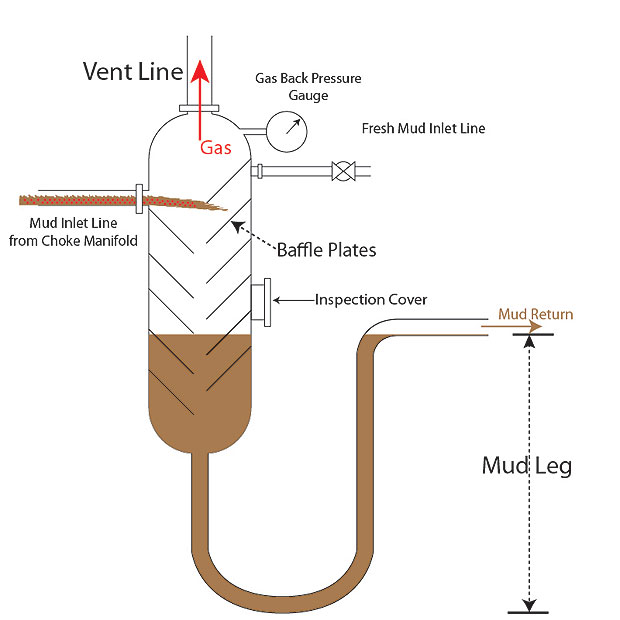
Figure 3 – Pipe Rams Cameron U Type (Courtesy of Cameron)

Variable Bore Rams (VBR)

Variable bore rams will seal around various size of pipe as opposed to a pipe rams which can seal only one size of pipe. The VBR will remove the need for multiple sets of pipe rams (one for each pipe size), only one set of Cameron VBRs will be required regardless of the sizes of pipe or hexagonal kelly. With a single set, it’s possible to receive backup for different sizes; for example, a common set 2-7/8″ × 5″ and 5″ × 7″. Depending on ram range and tool joint size, some will have a limited hang-off capacity. Using surface pressure, it may be possible to force the tool joint through the ram packer but only when the outside diameter (OD) doesn’t exceed the variable ram’s maximum capability.

Figure 4 -Variable Bore Rams (courtesy of SLB)

Within their VBR and VBR II range, the following variable bore rams for U, UM, and UL are provided by Cameron (see the table below);

For those who need different sizes, these may be available from other manufacturers.

Some key interesting features are as follows;

•   Proprietary seals (CAMRAM) are the standard for well

•   Steel reinforcing inserts – when the rams are closed, these will rotate inwards and add support for the rubber (sealed against the pipe).

•   As per NACE MR-01-75, they’ll be perfect for H2S service.

Shearing Blind Rams (SBR)

To contain wellbore pressure, shear/blind rams can actually act as blind rams after cutting the drillpipe; a recess accommodates the pipe stub. Before shearing and if the situation allows, the pipe needs to be in tension and stationary. In addition to this, some cases will require a manifold pressure of more than 1,500psi while operators need to be sure that the tool joint isn’t opposite the rams. In terms of the shear process itself, the size and grade of the pipe can both be limiting factors (even when maximum manifold pressures apply). Unfortunately, for sour service, not all models of blind/shear rams will be suitable.

With Cameron SBRs, the pipe is sheared in the hole before the lower section (of the sheared pipe) is bent and this allows the rams to seal and close. For normal drilling or completion operations, the SBRs may have a use in closing on an open hole. With this in mind, its features contain;

  • An ability to cut pipe several times while protecting the cutting edge.
  • Integrated cutting edge within the single-piece body.
  • Increased service life and reduced pressure for the rubber thanks to a large frontal area of the blade itself.
  • For critical service applications, H2S SBRs are available and these will boast hardened high alloy as the blade material.
  • All Cameron SBRs have CAMRAM top seals as standard.

With some similarities to SBRs, shearing blind rams called ‘DVS’ rams (double V shear) also exist and they have two main differences;

  • They offer the largest-possible blade width while still fitting within the existing ram bores.
  • After shearing, the lower section of the tubular will be folded with DVS rams and this allows a sealing between the lower blade and the blade packer.

Figure 5 – Double V Shear (courtesy of SLB)

Cameron U II Blowout Preventer

If you take the U BOP, and then make it suitable for subsea use, we find the Cameron U II BOP (suitable for 18-3/4-10,000 as well as 15,000psi WP sizes). Pressure-energised rams, just like other Cameron preventers, the seal can be maintained and the sealing force increased whenever hydraulic pressure is lost as the wellbore pressure acts on the rams. As wellbore pressure increases, seal integrity improves.

Important features of the U II BOP include;

  • On bonnet studs and nuts, the need for high makeup torque is eliminated with the bonnet seal carrier.
  • Even and accurate stud loading can be ensured consistently thanks to an internally ported hydraulic stud tensioning system.
  • Normally, hydrostatic pressure can cause the wedgelock to unlock; this is removed by a pressure balance chamber.
  • When actuating pressure is released and the ram is locked hydraulically, the rams can be held closed mechanically by hydraulically-operated locking wedgelocks (mechanisms).

Additionally, the design boasts a selection of rams depending on the application, hydraulically opening bonnets, and a forged body.

Figure 6 – U II Blowout Preventer (courtesy of SLB)

References

Cormack, D. (2007). An introduction to well control calculations for drilling operations. 1st ed. Texas: Springer.

Crumpton, H. (2010). Well Control for Completions and Interventions. 1st ed. Texas: Gulf Publishing.

Grace, R. (2003). Blowout and well control handbook [recurso electrónico]. 1st ed. Paises Bajos: Gulf Professional Pub.

Grace, R. and Cudd, B. (1994). Advanced blowout & well control. 1st ed. Houston: Gulf Publishing Company.

Watson, D., Brittenham, T. and Moore, P. (2003). Advanced well control. 1st ed. Richardson, Tex.: Society of Petroleum Engineers.

Watch, O., 2013. Offshore Well Blowout – Investigation Report. [online] Officer of the Watch. Available at: <https://officerofthewatch.com/2013/04/15/offshore-well-blowout/> [Accessed 8 August 2020].

Cable double-V shear rams. 2019. Cable double-V shear rams. [online] Available at: <https://www.slb.com/drilling/rigs-and-equipment/pressure-control-equipment/bop-rams/cdvs-ii-cable-double-v-shear-rams> [Accessed 21 June 2021].

The post Basic Understanding about Cameron U BOP – Rams Blow Out Preventer appeared first on Drilling Formulas and Drilling Calculations.

Introduction to Diverters in Well Control

$
0
0

Considering the danger of shallow steam or gas zones requires unique well control considerations. Whenever the necessary casing shoe integrity cannot be obtained due to the shallowness of the zones (before encountering pressure), a kick will need to be diverted because it cannot be shut-in. For this situation, a diverter shown in Figure 1 is a mandatory equipment to divert the undesirable flow to allow personal to have proceed the next plan; i.e., evacuation and/or dynamically kill a well.

Figure 1 - Diverter Package in Well Control (Courtesy of Cansco Dubai LLC)

Figure 1 – Diverter Package in Well Control (Courtesy of Cansco Dubai LLC)

By directing the flow from an unloading well, diverting allows physical damage to be limited to all equipment and rig personnel. With specialized procedures and equipment, the idea is to impose limited back pressure on the weak downhole formations. Although not strictly a well control procedure, diverting successfully will allow the well to be dynamically killed, to bridge over, or be depleted (without losing equipment or life).

Wherever possible, diverting needs to be avoided. In an ideal situation, if full shut-in will with a strong casing shoe should be chosen instead of a diverter. On conductor casing shoes, leak-off tests need to be performed to assess the likelihood of successfulness of shutting the well in. Any flow from the formation is likely to reach the surface in quick time since the gas is shallow and, therefore, the time available to detect the kick and then divert or shut-in is extremely small.

Purpose of Diverter System

A certain amount of protection can be provided by the diverter system before the rig can install the BOP onto the well. By design, diverter systems will direct the flow to a safe location by packing off around the drill string, Kelly, or casing. For the valves, they allow the well flow to be directed whenever the diverter has been actuated.

Figure 2 - Diverter Diagram

Figure 2 – Diverter Diagram

Diverter systems are often defined as a low pressure annular. As the name suggests, the flow cannot be stopped or shut-in with a diverter; the only goal is to direct the flow to a safe location away from the rig. To effectively remove the flow and well debris, the system must equip with a large internal diameter with sufficiently sized vent lines.

High Risk Operation

Associated with shallow gas, diverting presents serious risks. For the drilling industry, many incidents shows that shallow gas divert operations are more dangerous well control hazards than any other. Whether successful technically or not, all divert events are classified as blowouts by the US Minerals Management Service (MMS) because the very definition of a divert involves formation fluids in an uncontrolled flow. For the technical success of the diverting operation, the inherent risk needs to be managed carefully; the best management stance to risk will always be to avoid diverting at all costs.

How can diverting be prevented? Firstly, by not drilling through shallow gas. While seismic data can provide some help in avoiding shallow gas zones, drilling only where potential for shallow gas is non-existent is incredibly difficult. If drilling in this environment is entirely necessary, and the casing program cannot be designed to shut-in after kicks, not taking shallow kicks will be the only diverting avoidance technique possible.

While swabbed kicks are considered ‘avoidable’ kicks, hydrostatic imbalances that cause drilled kicks can be unavoidable with even the best planning. To reach technical success in these circumstances, an effective response plan needs to be in place and all elements of this plan need to be ready; this includes equipment, technique, people, and training.

For subsea and surface diverting, ‘Recommended Practices for Diverter Systems Equipment and Operations’ (Recommended Practice 64) is a reference document provided by the American Petroleum Institute (API). Considered the ‘API RP 64’, this is a useful resource for such events.

Criteria for Diverter or BOP

At the shoe, well integrity is often an issue with shallow casing strings and, in some cases, shutting in the well can cause too much pressure. Whenever a well with little/no shoe integrity is closed-in, this can cause formation fluids to broach to the surface or it can cause a shoe breakdown. When the shoe broaches, a bottom supported rig can be put into danger (along with its crew), including platform, jack-up, and land rig, but it won’t considered as dangerous for a floating vessel. When inadequate casing is present and a shallow gas kick is encountered in a bottom supported rig, diverting is the best alternative to shutting in.

To allow time for remedial action and potential evacuation, and to reduce the risk of damage, the flow needs to be directed as the well begins to unload. When shallow gas potential is seen, a BOP or modified BOP system should be installed before penetrating the formation. By doing this, proven well control procedures can be used. This can only occur when formation integrity will allow for the well to be killed (through the application of back pressure and/or shutting in).

When considering a diverter system over a BOP stack, there are two main considerations;

•   Diverting will be preferred when insufficient formation integrity means shut-in pressure would cause damage (when drilling below conductor). If the well were to be shut-in after a kick, the formation fluids would broach the casing shoe in this scenario.

•   When drilling below drive or structural pipe, diverting will be the chosen method.

As mentioned previously, wherever possible, a shut-in will always be the preferred method.

On the vent line, diverter systems should offer a full opening hydraulic valve. This valve can be opened automatically as the diverter closes when the control system is plumbed correctly, or it will add value to the closing diverter. According to industry best practices, hydraulic ball valves are the suggested types with full bore to the vent line and outlet.

Figure 3 - Diverter Systems – Surface Installations

Figure 3 – Diverter Systems – Surface Installations

API also recommend always testing upon installation; from opposite panel, a function test can occur every 24 hours. When installed, any valves and the diverter should be actuated as well as doing so at ‘appropriate times’ to ensure the system is working as expected. To ensure the lines aren’t plugged, fluid should also be pumped through the diverter lines during operation.

Diverting Operations and Equipment – Installation and Equipment Requirements

Below the mud line, a short string of drive pipe or large diameter casing can normally be installed when commencing a well in the water. On land locations, at a shallow depth, casing string can be set and cemented. With the casing or drive pipe in place, it acts as a seal to support the hydrostatic head of the fluid column – between the flow line outlet and the base of the casing. With the diverter installation occurring at the casing or drive pipe, either a low-pressure diverter is required or an annular preventer; if the latter, it requires sufficient internal bore to pass the tools used for drilling operation.

With the vent lines recommended by API RP 64, these extend between the outlets underneath the diverter and a safe space away from the well. The chosen location should allow for proper disposal of the fluid flowing from the well.

In place of proper diverters, some have previously used rotating heads or annular blowout preventers. This being said, it’s now possible to acquire special low pressure diverters in various sizes. In terms of the working pressure of the vent lines and the diverter, this isn’t too important because they’re actually sized to minimize well bore back pressure while diverting well fluids. For land and offshore uses, many Operator Companies will recommend a minimum ID of 10” for vent lines while a diameter is 12” is recommended for floaters.

References 

Cormack, D. (2007). An introduction to well control calculations for drilling operations. 1st ed. Texas: Springer.

Crumpton, H. (2010). Well Control for Completions and Interventions. 1st ed. Texas: Gulf Publishing.

Grace, R. (2003). Blowout and well control handbook [recurso electrónico]. 1st ed. Paises Bajos: Gulf Professional Pub.

Grace, R. and Cudd, B. (1994). Advanced blowout & well control. 1st ed. Houston: Gulf Publishing Company.

Watson, D., Brittenham, T. and Moore, P. (2003). Advanced well control. 1st ed. Richardson, Tex.: Society of Petroleum Engineers.

Cansco.com. 2019. Diverter Packages – Cansco Well Control. [online] Available at: <http://cansco.com/products/diverter-packages/> [Accessed 11 October 2021].


The post Introduction to Diverters in Well Control appeared first on Drilling Formulas and Drilling Calculations.

Risks and Equipment Considerations for Surface Diverting (Well Control)

$
0
0

Of all diverts, many studies show a failure rate of between 50% and 70%. According to the same studies, when it comes to well control issues, shallow gas blowouts is the leading cause of offshore rig damage and loss. On the US Outer Continental Shelf, the MMS agrees with these findings and has suggested a 46% failure rate between 1971 and 1991. Even though mandatory well control training was introduced during this period, the MMS has noted that a reduction in blowout frequency wasn’t experienced during this time.

Why have failure rates not declined?

For the most part, this is not about well control proficiency, it is the fact that drilling into a shallow gas zone is a lot more difficult to handle than typical well control.

Therefore, there needs to be a mindset of ‘when’ the diverter will fail as opposed to ‘if’. During a shallow gas divert, the ideal situation would see a depletion or bridging off before the system has a chance to fail. When it comes to the likelihood of the well bridging or depleting, this increases the longer a system is allowed to divert a shallow gas blow before failure.

Ultimately, three types of diverter failure exist;

  •  Excessive back pressure through the diverter system resulting in formation fracture
  • Formation fracture as a result of a failure in vent line valves (not opening)
  • Metal erosion

With the right-sized vent, the correct vent line valves, and actuating systems, the first two failures can normally be prevented. By following the necessary guidelines, as well as with the right maintenance, the risk of failure can be reduced; excessive back pressure shouldn’t occur, and the vent live valves shouldn’t be prevented from opening because of vent lines that are simply too small.

Metal Erosion

The likelihood of erosion will depend on several factors; the geometry of the diverter system, the type of fluid, fluid viscosity, and even the abrasiveness of particles entrained in the flow. For many erosion failures, the cause is undersized vent lines or turbulence resulting from poor vent line flow paths. Most common, turns in the vent line are the danger spots but they also occur at the diverter spool, downstream of valves or at valves themselves, and at flexible hose connections.

The reason why metal erosion is so difficult to control is because the geometry of the system is the only risk where drilling personnel have control. While the abrasiveness of the particles and the type of formation fluid cannot be controlled by personnel, the geometry of the system and permeability of the formation alongside pressure will decide the fluid viscosity rates.

Thanks to Louisiana State University (LSU) and a study on metal erosion, we can see that it’s influenced heavily by the type of formation fluid. The summaries are as follows;

  • Compared to liquid, gas causes metal erosion around 100 times faster.
  • The quantity of sand produced with the fluid is also a key component. Erosion rate increases as the amount of sand increases; however, there’s a point when high sand concentration is met, the sand will interfere with itself, and it will protect the metal instead of increasing erosion rate.
  •  Metal erosion is deeply affected by fluid viscosity since the square of the fluid viscosity is directly proportionate to erosion. What does this mean? Well, twice the fluid viscosity will lead to four times the erosion. When three times the viscosity, this creates nine times the erosion.
  • In terms of the geometry of the system, fluid velocity and turbulence can be reduced with larger-diameter straight vent line systems. Furthermore, a downhole restriction provided by smaller pilot hole sizes can limit fluid velocity too.

Diverting vs Shutting-In – Combination Stack

Depending on the formation integrity at the conductor shoe, the decision to shut-in or divert will be made. However, this cannot be known until the shoe is drilled out which means it’s a tricky decision of whether to nipple up a BOP stack (after cementing conductor casing) or a diverter. These days, combination diverter/BOP stacks can be nippled up on conductor casing and this allows a workaround of the problem. Once the conductor shoe has been tested, the correct decision can be made. According to API, before using a BOP stack, a competent shoe needs to be set and the LOT performed.

Otherwise, the problem can be avoided by rigging up a diverter system designed to enable full shut-in. This should allow diversion through large vent lines and it should allow circulation through a choke manifold and choke line. This can be achieved with two spools (one with large vent lines and one with kill/choke lines). Compared to a BOP stack, using a diverter in this way won’t allow for the same handling of pressure (or redundancy) but the flow rates are expected to be high while the surface pressures are generally expected to be low.

Figure 1 - Combined Stack

Figure 1 – Combination Stack

Diverter Spool

The diverter spool, for surface applications, must always equal or greater than the annular preventer in terms of pressure rating. Additionally, it should have at least a 10” vent line and two 10” minimum ID side outlets. As long as they’re swaged up to 10” at the spool, some MMS operations will allow for two 8” outlets. To install the divert valves, no other swages or adapters should be used. With some spools, they only have one outlet; in this case, it will need to be 10” and it will need to Tee into two 10” overboard vent lines. In an ideal scenario, two 10” outlets would be used with no swages.

What about onshore operations? Although local policies and regulations may affect this, the spool requires at least one 6” minimum ID outlet. As well as being inspected thoroughly to ensure integrity, the risk of leaks should be reduced by installing all bolts and new ring gaskets.

Figure 2 - Diverter Spool

Figure 2 – Diverter Spool (Courtesy of Cansco.com)

Diverter Valves

Immediately adjacent to the diverter spool, the diverter valves need to be installed and this should protect against valve/spool failures; often, washing can be an issue due to turbulence. With a minimum ID of 10” (or according to local regulations, if a large bore size), the valves should be full opening.

Figure 3 - Diverter Valve

Figure 3 – Diverter Valve

As erosion is accelerated by ID changes, a uniform internal diameter should be promoted by the design of the diverter vent line assembly; this includes valves, spool outlets, and vent lines. Although diverter valves haven’t necessarily been designed to endure shut-in wellbore pressure, sudden vent line plugging could cause this to happen. Over the years, the hydraulic gate valve has been tested extensively with BOP systems and should be chosen with the diverter system over the hydraulic ball valve.

Why choose hydraulic over pneumatic with valve operation?

  • Control station fluid and hydraulic fluid allow for consistency.
  • Compared to pneumatic operators in a similar service, hydraulic operators will always require a smaller operating chamber to develop more closing force.
  • If the rig air supply turns off or is depleted, hydraulic valves can still operate as normal.
  • Freezing issues are less common with hydraulic systems.
  • Compared to pneumatic tubing, hydraulic control lines are more resistant to damage thanks to their heavy-duty nature and high-pressure steel lines.
  • Leaks are easier to locate with hydraulic systems.

Malfunctioning of the divert valves is the most common reason for failure in the system, and a recent study now supports this. With this in mind, wherever possible, a hydraulic gate valve will be preferable. To ensure they aren’t seized up, all valves should be checked every 24 hours alongside the diverter itself.

To reduce lost return problems, some operations will need the installation of a booster pump on the drive pipe. Installed adjacent to the drive pipe, a remote valve will be required when this pump is being used; it should always have a pressure rating close to the system. When the diverter is closed, it needs to close automatically and therefore it needs to be tied into the diverter panel. If a booster pump is not closed automatically when the diverter valve is closed, it will increase wellbore and surface pressure and it can lead to fracturing formation or damaging surface equipment.

Diverter Vent Lines

Just as we saw with divert valves, overboard lines or diverter vent lines need to be set up with the same pressure as the system. Whenever a line plugs, it needs to withstand pressure while the opposite line is being opened. In terms of extent, the lines need to open beyond the edge of decking underneath. Since erosion can be caused by the change in flow direction, lines must be as straight as possible.

Wherever hard piping is possible, use these between the overboard lines and divert valves. If this isn’t an option, divert valves and overboard lines can be connected with flexible hoses. However, they also need to be consistent with the rest of the system in terms of pressure rating. Additionally, they need to be as straight and short as possible while allowing for connection with integral end couplings. While flexible lines can be used, collapsible hoses with dresser sleeves or hose clamps are not acceptable for this use. Since they’re going to experience severe forces, all overboard lines and hoses need to be anchored down securely.

Diverter Control Stations

When it comes to definition in consistency, one component seems to be lacking more than most; the control station. For the diverter system to work effectively, the control station needs to be simple to operate and easily accessible; with this in place, there’s very little room for error. As a remote station to the main accumulator station, Figure 4 shows an example.

Figure 4 - Diverter Control Station

Figure 4 – Diverter Control Station

Two levers in a panel will normally be contained within a typical diverter control station, and each would be labelled for simplicity. For the first lever, this controls the diversion of the flow overboard; as soon as it moves to ‘Divert’, the annular preventer will be closed by shifting the four-way valve on the main accumulator. Meanwhile, both overboard lines will be opened as the four-way valve for starboard and port divert valves shift on the main accumulator.

For the second lever, this normally controls the upwind overboard line. For instance, if we need to close a starboard valve which is in the upwind direction, the second lever is switched to ‘Port’ which opens the port divert valve (if closed) and simultaneously closes the starboard four-way valve on the main accumulator. What’s more, regardless of how these levers are operated, no combination will ever cause a shut-in in the well.

With one diverter control station on the rig floor, a separate station will be required somewhere away from the rig floor and in a safe position. Using the rig’s continuous air supply, the stations will be operated by air but they should also hold an air reserve bottle just in case the air supply on the rig is disrupted. Available at both control stations, the bottle should provide enough volume to function each operation twice.

Why offer two separate diverter control systems? In truth, there are several benefits to doing this.

  • The stored energy of the system is utilized by using the main accumulator system.
  • The control system’s only function is to control the divert operation.
  • The control lines going from the component to the unit are high pressure, permanently-installed steel lines.
  • With the previous point in mind, it will always be a permanent asset of the rig.
  • When diverting a well, the risk of human error is eliminated completely

References 

Cormack, D. (2007). An introduction to well control calculations for drilling operations. 1st ed. Texas: Springer.

Crumpton, H. (2010). Well Control for Completions and Interventions. 1st ed. Texas: Gulf Publishing.

Grace, R. (2003). Blowout and well control handbook [recurso electrónico]. 1st ed. Paises Bajos: Gulf Professional Pub.

Grace, R. and Cudd, B. (1994). Advanced blowout & well control. 1st ed. Houston: Gulf Publishing Company.

Watson, D., Brittenham, T. and Moore, P. (2003). Advanced well control. 1st ed. Richardson, Tex.: Society of Petroleum Engineers.

Cansco.com. 2019. Diverter Packages – Cansco Well Control. [online] Available at: <http://cansco.com/products/diverter-packages/> [Accessed 11 October 2021].

Bsee.gov. 2021. Experimental Study of Erosion Resistant Materials for Use in Diverter Components. [online] Available at: <https://www.bsee.gov/sites/bsee.gov/files/tap-technical-assessment-program/008cb.pdf> [Accessed 23 October 2021].

Bsee.gov. 2021. Integrity of Diverter System Under Abrasive and Multi Phase Flow. [online] Available at: <https://www.bsee.gov/sites/bsee.gov/files/tap-technical-assessment-program/008cb.pdf> [Accessed 23 October 2021].

The post Risks and Equipment Considerations for Surface Diverting (Well Control) appeared first on Drilling Formulas and Drilling Calculations.

Accumulators for Surface Well Control System and Requirements

$
0
0

The accumulator unit is one of the critical well control equipment and its main aim is to supply the pumps with atmospheric fluid while also storing high pressure operating fluid for operating BOP stack. In this article, we will learn about requirements of critical components of an accumulator unit including  accumulators, reservoir, pneumatic pump, electric motor driven pumps and hydraulic control manifold/valve & fitting.

Surface BOP Control Systems Equipment

Accumulator Bottles

For storing high pressure fluid, accumulators are pressure vessels (ASME coded). Depending on requirements, the accumulators can be found in all sorts of types, sizes, pressure ratings, and capacities. Most commonly, ‘float’ and ‘bladder’ accumulators are used which come in ball or cylindrical shapes. Furthermore, they can be top or bottom loading.

Figure 1 - Accumulator Bottles

Figure 1 – Accumulator Bottles

If bottom loading, servicing will require them to be removed from the accumulator unit. If top loading, both float and bladder can be removed while mounted on the accumulator unit. Without destroying their stamp of approval, both types of accumulators can actually be repaired in the field whenever necessary.

Reservoir Tank

For storing atmospheric fluid, a rectangle reservoir is normally provided for high pressure pumps. Boasting troubleshoot inspection ports, baffles, and drain/fill ports, the Maintenance section can be reviewed for standard cleaning and filling guidance. The reservoir should be able to keep twice capacity of the usable fluid required.

Figure 2 - Reservoir Tank

Figure 2 – Reservoir Tank

Accumulator Piping and valves

Connecting the accumulators/hydraulic manifold with the pump’s high pressure discharge lines, the piping/valve has an important role. In order to protect the accumulators and prevent over pressurizing, the piping should consist of isolator valves, Schedule 80 or 160 pipe (1 or 1 1/2 inches), and a relief valve (3,300psi). To help minimize leaks and line restrictions, cylindrical accumulators can be mounted onto machined headers.

Read more details about 4-way valve > 4-Way Valve Operation in Blow Out Preventer Accumulator (Koomey) Unit

Figure 3 – Valve and Piping

Air Pump Assembly

To provide high pressure operating fluid, one or more hydraulic pumps in the air pump assembly will be connected (parallel) to the accumulator for the BOP control system.

Figure 4 - Air Pump

Figure 4 – Air Pump Assembly

Electric Pump Assembly

Driven by an explosion-proof electric motor, the electric pump assembly should always contain a duplex (or triplex) reciprocating plunger pump. To provide high pressure operating fluid to the BOP control system, this should be connected to the accumulator piping. Not only is it available in different voltage ranges, a range of horsepower options can be found too.

Figure 6 - Electric Pump Assembly

Figure 6 – Electric Pump Assembly

Accumulator Requirements

General

Accumulator bottles are pressure-sealed containers that hold hydraulic fluid for use in blowout preventer closure. These containers store energy in the form of compressed nitrogen gas, which can be utilized to close the preventer quickly. In common usage, two accumulator bottles exist including ‘float’ and ‘separator’.

  • Float – To separate the hydraulic fluid and the nitrogen gas, a floating piston is utilized with the float type.
  • Separator – To effect the separation of hydraulic fluid and nitrogen gas, the separator type uses a flexible diaphragm.

Volumetric Capacity 

All blowout preventer closing units should include accumulator bottles with enough volumetric capacity to produce enough usable fluid volume with pumps turned off to close a maximum of 4 BOP rams and the annular preventer in the stack, as well as enough volume to open the hydraulic choke line valve (HCR). Additionally, the final pressure shall be more than Minimum Operating Pressure (MOP). This is referred to API STD53.

Between 200psi above the pre-charge pressure and the accumulator operating pressure, the amount of fluid recoverable from an accumulator is considered the ‘usable fluid volume’. The accumulator operating pressure is the pressure at which hydraulic fluid is charged into accumulators.

Minimum Operating Pressure (MOP)

Based on the latest requirement from API STD 53 late 2018, Minimum Operating Pressure (MOP) is defined as a minimum pressure differential required for a device to successfully perform its intended function in a particular environment. If the BOP stack contains a shear ram with no dedicated shear accumulator , the calculated MOP must include the maximum pressure required to shear and seal the pipe for that operation. However, if the system has a dedicated shear accumulator, there will be separate MOP figures which are one for shear rams and another one for pipe ram.

API 16D Bottle requirements

The primary accumulator system must be built so that the loss of a single accumulator, bank, or both does not result in a loss of more than 25% of the system’s overall capacity. To decrease the possibility of bladder damage, the pre charge pressure for bladder type accumulators should be larger than 25% of the system hydraulic pressure. The amount of pre-charge pressure varies based on the individual operational needs of the equipment and the operating environment.

Response Time

In terms of response time, 30 seconds is the limit for the closing unit closing each ram preventer. For annual preventers under 18 3/4 inches, closing time should never exceed 30 seconds; for annular preventers larger than 18 3/4 inches, 45 seconds is the maximum.

Operating Pressure and Pre-charge Requirements for Accumulators

When it comes to operating an accumulator bottle, the pressure should never exceed its rated working pressure. During the initial closing unit installation, each accumulator bottle’s pre-charge pressure should be measured; this should occur on each well before then being adjusted, wherever required. For accumulator pre-charge, nitrogen gas should be used only. Finally, during well drill operations, the pre-charge pressure should be checked regularly.

Requirements for Accumulator Valves, Fittings, and Pressure Gauges

Valving should be installed in multi-bottle accumulator banks to ensure bank isolation. Except when the accumulators are isolated for service, testing, or transporting, an isolation valve must have a rated working pressure at least equal to the designed working pressure of the system to which it is connected and must be in the open position. If needed, accumulater bottles can be fitted in banks with a capacity of around 160 gallons, with a minimum of two banks.

On each accumulator bank, the appropriate fittings and valves need to be provided since this allows for the attachment of a pressure gauge without having to take all accumulator banks away from service. For installation, there should always be an accurate pressure gauge available in order to measure the accumulator pre-charge pressure.

Closing Unit Pump Requirements

Requirements for Closing Unit Valves, Fittings, Lines, and Manifold

Pump Capacity Requirements

To perform the operation in this section to a required standard, every closing unit needs sufficient numbers and sizes of pumps. On the size of pipe in use, the pumps should be able to close the annular preventer while the accumulator system is isolated. The hydraulically-operated choke line valve should also be opened and a minimum of 200psi pressure above the accumulator pre-charge should be obtained on the closing unit manifold within around two minutes.

Pump Pressure Rating Requirements

Pumps must be installed in each closing unit to generate a discharge pressure equal to the closing unit’s rated working pressure.

Pump Power Requirement

At all times, closing unit pumps must have power so, when the closing unit manifold pressure decreases, the pumps start automatically; the decrease in pressure should be lower than 90% of the accumulator operating pressure before activating.

On each closing unit, two or three independent power sources should be ready with each having the ability to pump at a rate the Pump Capacity Requirements section suggests. When ‘dual source’ power systems are mentioned, this refers to air and electrical systems in general. The dual air or electric systems are acceptable but less preferred.

The dual power source systems are as follows:

  • A dual air and electrical system = a dedicated air compressor for an accumulator + a rig electrical generator to run electric pump
  • A dual air system = a dedicated air compressor for an accumulator + a rig electrical generator to run compressor
  • A dual air system = a dedicated air compressor for an accumulator + an air storage tank that is separated from both the rig air compressors and the rig air storage tank by check valves.
  • A dual electrical system = one electrical power from main generator + another one from a back up generator (emergency generator)
  • A dual air/nitrogen =a dedicated air compressor for an accumulator + bottles nitrogen gas.
  • A dual electrical/nitrogen = one electrical power from main generator + bottles nitrogen gas.

If surface pressures fall 200psi lower than originally expected, and if the drilled casing is set at less than 500 feet on shallow wells, the closing unit will not require a backup source of power.

Requirements for Closing Unit Valves, Fittings, Lines, and Manifold

Requires Pressure Rating

Between the BOP stack and the closing unit, all fittings and valves should have a rated working pressure equal or above the BOP stack’s working pressure (up to a maximum of 3,000psi) and should also be constructed with steel. For all test pressure requirements, these are available in API Spec 6A: Specification for Wellhead Equipment. Steel should also be used for all lines between the blowout preventer and closing unit; if not steel, an equivalent fire-resistant hose with flexibility. For the end connections, the stack pressure rating (up to 3,000psi) and rated working pressure should be equal.

Valves, Fittings, and Other Components Required

The following should be equipped with each installation;

  • Sufficient check valves for each closing unit, or shut-off valves to separate the accumulators and the closing unit pumps from the closing unit manifold; this should also allow for the isolation of the annular preventer regulator.
  • Full-opening valve for each closing unit in order to connect a separate operating fluid pump whenever required.
  • A pressure regulating valve for each closing unit in order to allow for manual control of the annular preventer operating pressure.
  • A regulating valve for each closing unit to control the ram type preventers operating pressure; they should also be equipped with a valve and by-pass line so the closing unit manifold can take the full accumulator pressure whenever required.
  • Accurate pressure gauges for each closing unit to indicate the closing unit manifold’s operating pressure; in relation to the annular preventer pressure regulating valve, both downstream and upstream can be important.
  • A full-opening plug valve for each annular preventer on both opening and closing lines. Not only should these valves be present, they need to be in the open position while installed adjacent to the preventer itself. When testing operating lines over 1,500psi, open position isn’t applicable if the annular preventer isn’t damaged at all.
  • All closing unit control valves should be marked to show the position of the valves as well as which choke line valve or preventer each valve operates. During drilling operations, the BOP control valves should be ‘open’ rather than on ‘neutral’ or ‘block’. During normal operations, the choke line valve should be closed. To avoid accidental operation, the control valve in charge of the blind rams should be covered (over the manual handle). Finally, if the remote unit is activated, the handle shouldn’t be covered to the point where it stops the ram function from working.

Requirements for Closing Unit Fluids and Capacity

For the closing unit control operating fluid, either hydraulic oil or fresh water containing a lubricant should be used. When a closing unit fluid contains water and the expected ambient temperature is below 32F, glycol shall be added. Due to the likelihood of seal damage, there are several substances not recommended for the task; this includes chain oil, diesel oil, motor oil, and kerosene. The reservoir tank capacity must be at least 2 times of usable fluid used in the system.

Closing Unit Location and Remote Control Requirements

For the main pump accumulator, this needs a safe storage space while also being accessible in an emergency for all rig personnel. Additionally, it should prevent a flow back to the reservoir from the operating lines and it should prevent excessive drainage. To compensate for flow back in the closing lines when the main pump accumulator is located some way below the BOP stack, additional accumulator volume can be added.

Control panels should be equipped with each installation to allow the driller to control each control valve and blowout preventer, from a position easily accessible; this point should also be some distance from the rig floor.

References

Cormack, D. (2007). An introduction to well control calculations for drilling operations. 1st ed. Texas: Springer.

Crumpton, H. (2010). Well Control for Completions and Interventions. 1st ed. Texas: Gulf Publishing.

Grace, R. (2003). Blowout and well control handbook [recurso electrónico]. 1st ed. Paises Bajos: Gulf Professional Pub.

Grace, R. and Cudd, B. (1994). Advanced blowout & well control. 1st ed. Houston: Gulf Publishing Company.

Watson, D., Brittenham, T. and Moore, P. (2003). Advanced well control. 1st ed. Richardson, Tex.: Society of Petroleum Engineers.

The post Accumulators for Surface Well Control System and Requirements first appeared on Drilling Formulas and Drilling Calculations.

Understanding the Dynamics of Tripping Pipe in Well Completions and Workovers

$
0
0

Tripping pipe into and out of a well constitutes a commonplace activity in completion and workover operations. However, alarming statistics reveal that a significant number of kicks occur during these trips. Consequently, gaining a profound understanding of the fundamental principles associated with tripping is imperative in completion and workover endeavors.

What is Surge?

The descent of tubing into the well (tripping in) generates pressure exerted at the well’s bottom. As the tubing is introduced into the well, the well’s fluid must ascend to exit the volume being encroached upon by the tubing. This simultaneous downward movement of the tubing and upward movement of the fluid, often referred to as the piston effect, leads to a rise in pressure at any given point in the well. This pressure escalation is commonly termed surge pressure.

What is Swab?

Conversely, the ascent of tubing from the well (tripping out) impacts the pressure applied at the well’s bottom. When withdrawing pipe from the well, fluid must descend to fill the void left by the tubing. The collective result of the tubing’s upward movement and the fluid’s downward movement is a reduction in bottom hole pressure. This pressure decrease is known as swab pressure.

Key Parameters Affecting Surge and Swab

Both surge and swab pressures are influenced by several key parameters:

  • Velocity of the pipe, or tripping speed
  • Wellbore geometry (annular clearance between tools and casing, tubing open-ended or closed off)
  • Fluid viscosity
  • Fluid density
  • Fluid gel strength

It is evident that higher tripping speeds lead to increased surge and swab pressure effects. Similarly, greater fluid density, viscosity, and gel strength amplify the tendency for surge and swab effects. Additionally, downhole tools like packers and scrapers, characterized by minimal annular clearance, further accentuate surge and swab pressure effects.

Accurate determination of surge and swab pressures can be achieved through the utilization of drilling hydraulic calculator programs, or by referencing hydraulic manuals.

References

Cormack, D. (2007). An introduction to well control calculations for drilling operations. 1st ed. Texas: Springer.

Crumpton, H. (2010). Well Control for Completions and Interventions. 1st ed. Texas: Gulf Publishing.

Grace, R. (2003). Blowout and well control handbook [recurso electrónico]. 1st ed. Paises Bajos: Gulf Professional Pub.

<p>The post Understanding the Dynamics of Tripping Pipe in Well Completions and Workovers first appeared on Drilling Formulas and Drilling Calculations.</p>

Understanding Kick and Influx in Drilling and Completion Operations

$
0
0

In the realm of well control, encompassing both drilling and completion operations, the terms kick and influx hold significant importance. This article aims to explain the distinctions between these two terms, offering insights into their unique characteristics within the context of well control.

What is Kick?

Kick : A kick is the unwanted influx of formation fluid into the wellbore, typically occurring when the pressure exerted by the column of drilling fluid is insufficient to overcome the pressure from fluids in a permeable formation. Unintentional kicks, such as drilling into abnormally pressured formations or inadequately maintaining hole fullness during tripping, constitute the majority of kick incidents. Vigilance throughout rig operations is crucial to prevent kicks, especially considering historical industry data indicating a higher likelihood of kicks during rig operations.

While intentional flows of formation fluids are desirable in certain situations, such as during well production or drill stem testing, unintentional kicks during completion, workover, or drilling operations pose a significant threat to well control if immediate action is not taken.

What is Influx?

 Influx: An influx is the entry of formation fluid into the wellbore, with varying potential to reduce hydrostatic pressure below formation pressure. Regardless of its impact on pressure, an influx signals that the exposed, porous, and permeable formation’s pressure has surpassed the adjacent wellbore pressure at some point. Failure to promptly recognize an influx, especially one involving gas, can lead to further reductions in hydrostatic pressure, ultimately risking the loss of well control.

Wells experience kicks when the reservoir pressure of an exposed, permeable formation exceeds the wellbore pressure at that depth. Several factors contribute to this underbalanced condition, including:

  • Low-density drilling fluid.
  • Abnormal formation pressure.
  • Swabbing.
  • Insufficient hole fullness during trips.
  • Lost circulation.

References

Cormack, D. (2007). An introduction to well control calculations for drilling operations. 1st ed. Texas: Springer.
Crumpton, H. (2010). Well Control for Completions and Interventions. 1st ed. Texas: Gulf Publishing.
Grace, R. (2003). Blowout and well control handbook [recurso electrónico]. 1st ed. Paises Bajos: Gulf Professional Pub.

<p>The post Understanding Kick and Influx in Drilling and Completion Operations first appeared on Drilling Formulas and Drilling Calculations.</p>


Understanding Factors Leading to Low Density Drilling Fluid and Potential Well Control Events

$
0
0

The density of drilling fluid plays a critical role in well control during both drilling and completion operations. This article aims to explore the various factors that can result in low-density drilling fluid, potentially leading to well control challenges.

Accidental Dilution and Fluid Addition

Maintaining the hydrostatic pressure necessary to balance or slightly exceed formation pressure requires constant monitoring and adjustment of drilling fluid density. Accidental dilution of drilling fluid with makeup water in surface pits or the addition of low-density formation fluids into the mud column can reduce fluid density, triggering a potential kick. Rigorous vigilance in monitoring mud pits is essential to ensure the required fluid density is consistently maintained.

Gas Cutting

Large volumes of gas in the returns can cause a drop in the average density and hydrostatic pressure of the drilling fluid. Notably, gas cutting often occurs in an overbalanced condition downhole. If a formation containing gas is drilled, the gas within drilled cuttings can expand as it moves up the annulus, leading to gas cutting at the surface. Detecting this is crucial, as a flowing well indicates a kick, necessitating immediate well shut-in and initiation of the proper kill procedure.

Oil or Saltwater Cutting

Invasions of oil or saltwater from drilled cuttings or swabbing can reduce the average mud column density, causing a drop in mud hydrostatic pressure. While the effect of these liquids on average density is less pronounced than gas, the impact on bottomhole pressure can be substantial. Liquids, being less compressible, result in uniform density reduction throughout the mud column.

Settling of Mud Weighting Materials

The settling of desirable solids or drilled cuttings in a mud can significantly reduce mud density, affecting hydrostatic pressure. Barite sag, more prevalent in highly deviated wells, requires a combination of sound mud design and operational practices for management.

Loss of Equivalent Circulating Density (ECD)

Shutting down pumps during drilling connection can lead to a reduction in dynamic bottomhole pressure, causing the loss of ECD. This loss can allow formation fluids to enter the wellbore, known as “connection gas.” Observation of connection gas is an indication that static mud overbalance is lost, necessitating a potential increase in mud weight.

Cementing Operations

Improper cement mixing, lost circulation, or casing float equipment failure can compromise cement density and reduce hydrostatic pressure, leading to well control issues.

Cement Slurry Transition

As cement transitions from a slurry to a solid state, there’s a temporary reduction in hydrostatic pressure due to self-supporting cement solids before the structure becomes impermeable. This can potentially lead to an influx.

Closely monitoring the well throughout all phases of drilling, completion, and cementing operations is imperative for preventing and mitigating well control events. Nurturing a proactive approach ensures the integrity and safety of the wellbore.

To prevent well control events caused by low drilling fluid density, it’s essential to:

  • Maintain strict pit discipline and monitor fluid properties regularly.
  • Use appropriate mud additives to prevent gas cutting and control fluid rheology.
  • Monitor for oil or saltwater invasions and address them promptly.
  • Implement proper mud design and operational practices to minimize barite sag.
  • Maintain pumps running during pipe connections to avoid ECD loss.
  • Exercise caution during cementing operations and closely monitor pressure changes.

References

Cormack, D. (2007). An introduction to well control calculations for drilling operations. 1st ed. Texas: Springer.
Crumpton, H. (2010). Well Control for Completions and Interventions. 1st ed. Texas: Gulf Publishing.
Grace, R. (2003). Blowout and well control handbook [recurso electrónico]. 1st ed. Paises Bajos: Gulf Professional Pub.

<p>The post Understanding Factors Leading to Low Density Drilling Fluid and Potential Well Control Events first appeared on Drilling Formulas and Drilling Calculations.</p>

What are HCR Valves?

$
0
0

An HCR valve, also recognized as a High Closing Ratio valve, is a specialized type of gate valve widely employed in well control systems, particularly within the blowout preventer (BOP) stack. Its purpose is to deliver a dependable and efficient method for managing wellbore pressure and averting uncontrolled fluid flow during drilling, completion, and production activities.

Distinguished by a remarkable closing ratio, which represents the ratio of fluid pressure upstream of the valve to the hydraulic pressure needed for closure, HCR valves excel in sealing against elevated wellbore pressures, even in the face of sudden pressure surges.

Typically featuring a double-acting design, HCR valves possess two hydraulic chambers that can be pressurized for both valve opening and closure. This dual-system redundancy ensures continued operability, even if one hydraulic system encounters a failure. Operating at a typical pressure of 1,500 psi, HCR valves are engineered with a rising stem design, offering enhanced control during operations. Unlike some valve designs, HCR valves do not incorporate back-seating allowance, emphasizing their commitment to reliable and secure fluid control.

Engineered to endure challenging wellbore conditions, such as high temperatures, corrosive fluids, and abrasive sand, HCR valves are crafted from robust materials like forged steel or stainless steel. Protective coatings are applied to resist corrosion, enhancing their durability.

As integral components of well control systems, HCR valves play a pivotal role in ensuring the safety of personnel and environmental protection during drilling and production operations. Their high closing ratio, redundant systems, and robust design collectively contribute to their reliability and effectiveness in managing wellbore pressure and preventing uncontrolled fluid flow.

References

Cormack, D. (2007). An introduction to well control calculations for drilling operations. 1st ed. Texas: Springer.
Crumpton, H. (2010). Well Control for Completions and Interventions. 1st ed. Texas: Gulf Publishing.
Grace, R. (2003). Blowout and well control handbook [recurso electrónico]. 1st ed. Paises Bajos: Gulf Professional Pub.

<p>The post What are HCR Valves? first appeared on Drilling Formulas and Drilling Calculations.</p>

What is a Back Pressure Valve (BPV)?

$
0
0

A Back Pressure Valve (BPV), also known as a tubing plug, serves as a one-way check valve typically placed within a specially machined profile in the tubing hanger or plug bushing. Its primary function is to impede the flow of fluids and gases through the hanger while permitting the pumping of fluid into the tubing string. These valves find application in various well operations such as removing the production tree, facilitating the initial nipple up of the Blowout Preventer (BOP) stack, installing the tree during the nippling down of the BOP stack, and handling heavy lifts over the wellhead.

The installation or removal of BPVs can be carried out with either the tree or BOP stack nipple up on the tubing head. Moreover, they can be installed with or without pressure on the tubing. If the BPV needs to be installed through the tree with pressure on the well, a lubricator is necessary. Wellhead manufacturers offer diverse designs for Back Pressure Valves, which depend on the size and make of the hanger and wellhead. It’s crucial to note that only personnel specifically trained by wellhead manufacturers should undertake the installation and removal of these valves.

There are typically two types of BPVs: type “B” and type “H,” illustrated in the diagram below. Both types fulfill the same function. The choice between type “B” and “H” depends on the tubing hanger models. Some hangers may be equipped with type “B,” while others may require type “H.” Therefore, wellhead manufacturers can provide guidance on which types of tubing hangers are suitable for specific models.


References

Cormack, D. (2007). An introduction to well control calculations for drilling operations. 1st ed. Texas: Springer.
Crumpton, H. (2010). Well Control for Completions and Interventions. 1st ed. Texas: Gulf Publishing.
Grace, R. (2003). Blowout and well control handbook [recurso electrónico]. 1st ed. Paises Bajos: Gulf Professional Pub.


<p>The post What is a Back Pressure Valve (BPV)? first appeared on Drilling Formulas and Drilling Calculations.</p>

What are Surface Controlled Subsurface Safety Valves (SCSSV)?

$
0
0

Surface Controlled Subsurface Safety Valves (SCSSV) are a critical component of well completions, preventing uncontrolled flow in the case of catastrophic damage to wellhead equipment. SCSSV’s are strategically positioned within the tubing string beneath the surface, or mudline in offshore scenarios. Their primary function is to automatically close and secure the well in the event of a catastrophic incident at the surface that poses a risk of severe damage or loss to the wellhead. These valves are governed by a slender steel control line, running externally from the surface down to the valve. In the unfortunate scenario where the wellhead sustains significant damage, leading to the rupture of the control line, the resulting loss of pressure prompts the valve to close, effectively sealing off the tubing. The image below show the actual SCSSV prepared for completion string.

Certainly! Here's a rewritten version of the article: Surface Controlled Subsurface Safety Valves (SCSSV)


Certainly! Here’s a rewritten version of the article:
Surface Controlled Subsurface Safety Valves (SCSSV)

There are primarily 2 designs for these valves: wireline retrievable and  tubing retrievable. Wireline retrievable valves offer the advantage of extracting and servicing or replacing the major components of the valve (excluding the body) without the need to pull the entire tubing string from the well. On the other hand, the tubing retrievable model necessitates the removal of the tubing string from the well to gain access to the valve. These valves, often referred to as “flapper type,” can be secured in the open position using wireline tools. This facilitates access to the tubing string beneath the valve, enabling additional wireline operations as needed.

Surface Controlled Subsurface Safety Valves (SCSSV) can be called in different names ie Tubing Retrievable Valve (TRSV), Down Hole Safety Valve (DHSV), Sub Surface Safety Valve (SSSV). If you see these names, they are  (SCSSV).

References

Cormack, D. (2007). An introduction to well control calculations for drilling operations. 1st ed. Texas: Springer.
Crumpton, H. (2010). Well Control for Completions and Interventions. 1st ed. Texas: Gulf Publishing.
Grace, R. (2003). Blowout and well control handbook [recurso electrónico]. 1st ed. Paises Bajos: Gulf Professional Pub.

<p>The post What are Surface Controlled Subsurface Safety Valves (SCSSV)? first appeared on Drilling Formulas and Drilling Calculations.</p>

What are differences between Back Pressure Valve (BPV) and Two-Way Check Valve (TWCV)?

$
0
0

Learn key differences between Back Pressure Valve (BPV) and Two-Way Check Valve (TWCV) so you can choose the right one for a particular operation.

Back Pressure Valve (BPV)

A Back Pressure Valve (BPV), also known as a tubing plug, typically functions as a one-way check valve and is placed in a specially machined profile within the tubing hanger or plug bushing. Its purpose is to block the passage of fluids and gases through the hanger while still permitting the injection of fluid into the tubing string. These valves are deployed in the well to facilitate the removal of the production tree, enable the initial connection of the Blowout Preventer (BOP) stack, support the installation of the tree during the descent of the BOP stack, and during heavy lifts over the wellhead.

Back Pressure Valve (BPV)

Back Pressure Valve (BPV)

Two Way Check Valve (TWCV)

Two-way check valve serves as back pressure valves, designed to provide a seal in both directions. It is employed for testing Blowout Preventers (BOPS) and the tree during the initial connection. This valve can be threaded and seated into the tubing hanger. Alternatively, it may be of a profile type and installed by wireline into a landing nipple with a matching profile.

With Two-way check valve, it limits circulating capability, so it is not normally used in live wells which possibly have a chance for circulation down the string. Additionally, it will not hold pressure at very low pressure since its mechanism inside a two-way check valve need to have pressure to push it to seal the pressure.

Two Way Check Valve (TWCV)

Two Way Check Valve (TWCV)

The table below show the comparison between Back Pressure Valve (BPV) and Two Way Check Valve (TWCV).

Objectives Back Pressure Valve (BPV) Two Way Check Valve (TWCV)
Install before landing tubing hanger Yes ✅ No❌
Install before removal of production tree Yes ✅ No❌
Install before testing BOP No❌ Yes ✅
Install before testing Xmas tree No❌ Yes ✅
Well required circulation or injection Yes ✅ No❌
Hold pressure both direction No❌ Yes ✅
Hold pressure only one direction Yes✅ No❌

References

Cormack, D. (2007). An introduction to well control calculations for drilling operations. 1st ed. Texas: Springer.
Crumpton, H. (2010). Well Control for Completions and Interventions. 1st ed. Texas: Gulf Publishing.
Grace, R. (2003). Blowout and well control handbook [recurso electrónico]. 1st ed. Paises Bajos: Gulf Professional Pub.

<p>The post What are differences between Back Pressure Valve (BPV) and Two-Way Check Valve (TWCV)? first appeared on Drilling Formulas and Drilling Calculations.</p>

Viewing all 117 articles
Browse latest View live


<script src="https://jsc.adskeeper.com/r/s/rssing.com.1596347.js" async> </script>